Home/
Registry/
Suzuki/
Bandit S/
2000-2005/
“Bandit - SOLD”/
Photo
supermotors.net/registry/media/485172
2003 Suzuki Bandit S Clutch Exploded Parts Diagram - Assembly Callouts
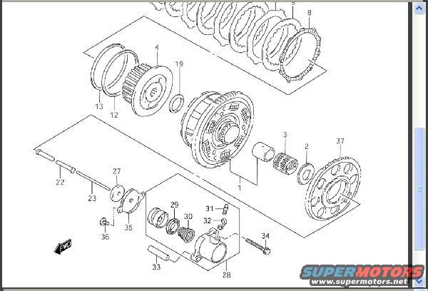
Exploded parts diagram of an automatic transmission clutch assembly with numbered callouts for clutch plates, drum and related components.
Part of 2000-2005 Suzuki Bandit S Exploded Parts Diagrams
This document is a scanned exploded parts diagram, filed as "clutch.JPG" for a 2003 Suzuki Bandit S. It illustrates a motorcycle clutch assembly and clutch release mechanism in exploded view. The drawing shows the clutch plate stack (items 5 and 8), the clutch center/hub assembly (item 1) with its needle bearing (3) and washer (2), a primary driven gear/sprocket (37), a small splined gear (4) with associated rings (12, 13, 19), clutch push rods (22, 23), a release lever and plate (27, 35, 36), and a hydraulic-style clutch release cylinder assembly including the body (28), piston with seal (29), spring (30), bleeder fitting (31, 32), pin (33), and mounting bolt (34). A "FWD" arrow indicates the forward orientation of the assembly on the machine. The diagram contains only numeric callouts, there is no legend, parts list, part numbers, or torque specifications visible, so a reader can learn the relative position, orientation, and assembly order of clutch components, but must cross-reference the callout numbers against a separate parts fiche to obtain part numbers. The scan is clean and all callout numbers are legible.
Is this accurate? Sign in to help verify it.
Frequently asked questions
- What does this diagram show?
- An exploded view of a clutch assembly, including the clutch plate stack, clutch hub, needle bearing, driven gear/sprocket, push rods, release lever, and a clutch release cylinder with piston, spring, and bleeder fitting.
- Does the diagram include part numbers or a parts list?
- No. Only numeric callouts (1-5, 8, 12, 13, 19, 22, 23, 27-37) appear; there is no legend or part-number table in the image.
- Which callout identifies the clutch plates?
- Item 5 points to the bracketed stack of clutch plates at the upper right, with item 8 marking the large splined plate at the end of the stack.
- Which items make up the clutch release cylinder assembly?
- Item 28 is the cylinder body, 29 the piston with seal, 30 the spring, 31 and 32 the bleeder fitting parts, 33 a pin/rod, and 34 the mounting bolt.
- How is the assembly oriented?
- An arrow labeled "FWD" at the lower left of the diagram indicates the forward direction of the assembly.
Comments
More from this build
No comments yet.