This document details steering column adjustments and alignment for F-100-350, Bronco, and Econoline vehicles.
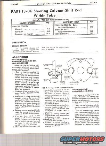
I 3-06- 1 Steering ColumnShift Rod Within Tube 13-06-1 PART 13-06 Steering Column-Shift Rod Within Tube Applies To F-IOO350, Bronco and Econoline Only COMPONENT INDEX Page COMPONENT INDEX Page STEERING COLUMN STEERING COLUMNCont. Alignment OB-I Removal and Installation ............ 06-2 D r' tio OBI STEERING WHEEL E39 'p n ' ' ' ' ' ' ' ' ' " ' Removal and Installation . _. 06-2 DIsassemvaandAssemblv - .......... 06-5 SPECIFICATIONS . . . . . . . .. 06-5 DESCRIPTION STEERING COLUMN The F-100-350, Bronco and Econoline, vehicles are equipped with columns which are designed with the shift tube within the column tube (Figs. 3, 4 and 5). ADJUSTMENTS STEERING COLUMN ALIGNMENTmoo THRU 350 (4x2) AND BRONCO Before checking the steering gear adjustments, eliminate any steering column tube and steering shaft stress or misalignment as follows: 1. Check the flexible coupling for clearance between the slots and the coupling safety pins. The pins must be centered in the slots. If the clearance is incorrect, loosen the 2 nuts that secure the steering shaft ange to the exible coupling. If the exible coupling has been driven in a non-at condition for more than 12,000 miles, it is recommended that it be replaced during this adjustment. . Loosen the 3 steering column lower support bracket bolts and the bracket clamp. . Remove the 2 screws attaching the modesty cover to the instrument FLEXIBLE COUPLING SAFETY PINS STEERING SHAFT FLEXIBLE COUPLING FLANGE .DIOINCH .O1OINCH SHIM SHIM COUNTER CLOCKWISE CLOCKWISE ROTATON STEERING ROTATION GEAR 3/32 INCH CONCAVE STEERING SHAFT UPWARD LOWER FLANGE 622274: the exible coupling is in the at plane, then tighten the 2 screws that attach the steering column to the instrument panel and torque to 1015 ft1b. 7. Replace the modesty cover to the panel and remove the modesty cover. instrument panel and tighten the 2 Loosen the 2 screws attaching the i . screws to secure the modesty cover to steering column to the instrument i - the instrument panel. panel, and allow the steering column . . . 8. Locate the steering column lower to drop 1/8 inch from the instrument k panel. support brac et snugly on the 4. Grip the steering wheel and briskly String}: 1::ng 3;? Stetdafrgmg shake the steering column to allow ? $2 Sift-1b a e c P relaxation 0f stress or misalignment. 9. Tighten the steering column lower 5. With the front wheels in the support bracket to the dash panel and straight-ahead position, check the torque to 12-18 ft_1b flexible coupling clearance as in 10. Road test the vehicle to check for Step 1. If the 2 nuts were loosened correction of the problem. in Step 1, tighten them to ll.Recheck the exible coupling for specified torque, of 11-21 ft-lbs. minimum slot and coupling safety pin 6. Move the column up or down until clearance and atness. FIG. 1 Steering Column Alignment-Econoline STEERING COLUMN ALIGNMENTECONOLINE Any stress or misalignment in the steering column tube and steering shaft should be eliminated before checking the steering gear adjustments. 1. Remove the steering column modesty cover. Loosen the steering columnetobrake and clutch support bracket bolts (Fig. 5). Loosen the steering column opening cover plate-to-dash panel bolts, and loosen the column lower clamp. Check the exible coupling retaining nuts to be sure that they are tight. With the front wheels in the straight ahead position, pull the steering column upward until the exible coupling is in a position between at 2.
Comments
More from this build
No comments yet.