Ford F-100-F-350 Steering Column & Wheel Removal/Installation - Shop Manual
Reference · 1975-1979 F-150All 5 service procedures


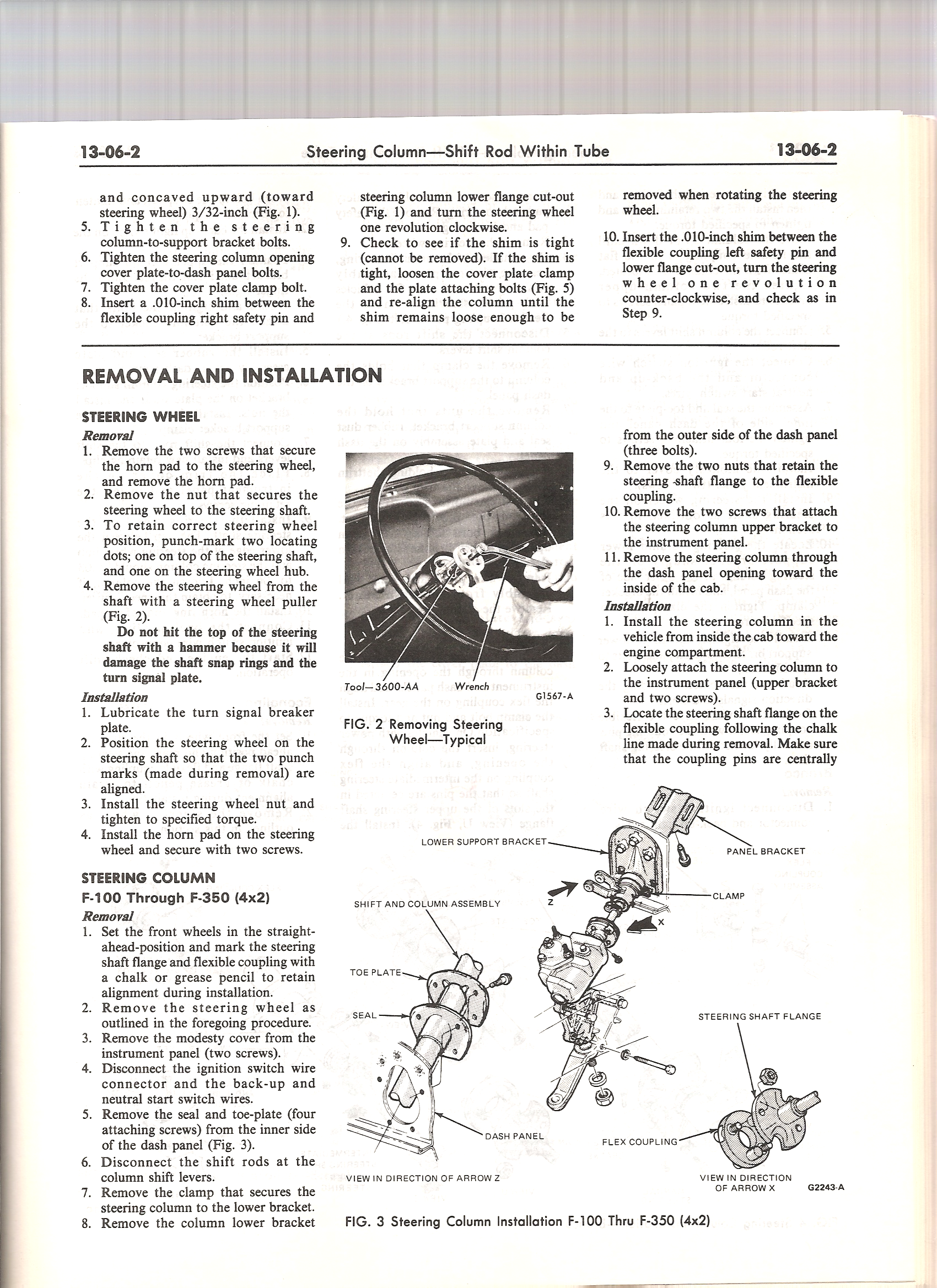
Ford service-manual page 13-06-2 detailing steering-wheel removal (horn pad, retaining nut, alignment punch-marks) and steering-column removal for F-100 through F-350 (4x2), with flexible-coupling shim alignment steps.
Part of 1975-1979 Ford F-150 Service Procedures
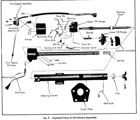
This is page 13-06-2 of a Ford truck shop manual, covering the section "Steering Column: Shift Rod Within Tube." The top of the page finishes a column alignment procedure that uses.010-inch shims placed between the flexible coupling safety pins and the steering column lower flange cut-outs, with the steering wheel rotated one revolution in each direction to verify the shims remain loose. The main body, titled REMOVAL AND INSTALLATION, gives step-by-step steering wheel removal and installation (horn pad screws, steering wheel nut, punch-marking for alignment, use of a steering wheel puller Tool, 3600-AA, and a warning not to hammer the shaft to avoid damaging snap rings and the turn signal plate). It then details steering column removal and installation for F-100 through F-350 (4x2) trucks: marking the shaft flange and flex coupling with chalk, removing the modesty cover, disconnecting the ignition switch and back-up/neutral start switch wires, removing the seal and toe-plate, shift rods, clamp, brackets, and withdrawing the column through the dash panel into the cab. Figure 2 shows steering wheel removal; Figure 3 is an exploded diagram of the steering column installation labeling the lower support bracket, panel bracket, shift and column assembly, clamp, toe plate, seal, dash panel, steering shaft flange, and flex coupling.
Is this accurate? Sign in to help verify it.
Frequently asked questions
- How do you remove the steering wheel on a Ford F-100 through F-350?
- Remove the two screws securing the horn pad, remove the nut that secures the wheel to the steering shaft, punch-mark two locating dots (one on the shaft, one on the hub) to retain position, then pull the wheel off with a steering wheel puller (Tool: 3600-AA shown in Fig. 2). Do not hit the top of the steering shaft with a hammer, as it will damage the shaft snap rings and turn signal plate.
- How is steering column-to-flex coupling alignment checked?
- Insert a.010-inch shim between the flexible coupling safety pin and the steering column lower flange cut-out, turn the steering wheel one revolution (clockwise for the right pin, counter-clockwise for the left pin), and check that the shim stays loose enough to be removed. If it's tight, loosen the cover plate clamp and plate attaching bolts and re-align the column.
- What must be disconnected before removing the steering column on an F-100 through F-350 (4x2)?
- Disconnect the ignition switch wire connector, the back-up and neutral start switch wires, the shift rods at the column shift levers, remove the seal and toe-plate (four screws), the lower bracket clamp, the lower bracket (three bolts), the two nuts retaining the steering shaft flange to the flexible coupling, and the two upper bracket screws at the instrument panel.
- How is alignment of the steering shaft flange preserved during column removal?
- Before removal, set the front wheels straight ahead and mark the steering shaft flange and flexible coupling with chalk or a grease pencil; on installation, locate the flange on the flex coupling following that chalk line and make sure the coupling pins are centrally located.
- Which direction is the steering column removed from the truck?
- The column is removed through the dash panel opening toward the inside of the cab, and installed from inside the cab toward the engine compartment.

No comments yet.