Home/
Registry/
Isuzu/
VehiCROSS/
1997-2001/
2001 Isuzu Vehicross/
Photo
supermotors.net/registry/media/554059
2001 Isuzu VehiCROSS Power Steering Pump Exploded Parts Diagram

Reference · 1997-2001 VehiCROSSAll 1 exploded parts diagrams
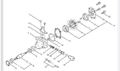
Exploded parts breakdown drawing of a pump or valve assembly with numbered components and fasteners.
Part of 1997-2001 Isuzu VehiCROSS Exploded Parts Diagrams
This document is an exploded parts diagram of a power steering pump assembly, uploaded as applicable to a 2001 Isuzu VehiCROSS. The line drawing shows the pump fully disassembled with 27 numbered callouts identifying individual components, including the main pump housing, drive shaft with bearing, snap ring, washers and spacers, the rotor/vane cartridge group with cam ring, pressure plate, gaskets and O-rings, the rear cover with four mounting bolts, the flow control valve with its spring and sealing washers, an outlet fitting/union, and what appears to be a pressure switch with a wiring pigtail. The diagram contains no legend, part numbers, torque specifications, or descriptive text, only the numeric callouts 1 through 27. A reader can use this diagram to understand the assembly order and relative position of every component in the pump, which is useful when rebuilding or resealing the pump, replacing the flow control valve, shaft seal, bearing, or internal cartridge, or identifying which numbered part to order from a corresponding parts list (not included in this scan). Because the drawing itself carries no year, model, or engine identification, its exact vehicle applicability cannot be confirmed from the document alone.
Is this accurate? Sign in to help verify it.
Frequently asked questions
- What does this diagram show?
- An exploded view of a power steering pump assembly with 27 numbered callouts identifying its components, including the housing, shaft, rotor/vane group, rear cover, flow control valve, and fittings.
- Does the diagram include part numbers or a parts legend?
- No. The diagram contains only numeric callouts (1-27) with no legend, part numbers, or text descriptions.
- How many bolts hold the rear cover on the pump?
- The drawing shows four bolts (callout 20) at the rear cover/end plate area.
- Can I see the order of internal pump components?
- Yes. The exploded view shows the assembly sequence: housing (4), gaskets/O-rings (12, 13, 18), pressure plate (15), rotor/vane cartridge (16), and rear cover (19) with bolts (20), plus the flow control valve group (21-25) and outlet fitting (26).
No comments yet.