Home/
Registry/
Volkswagen/
Scirocco/
1982-1988/
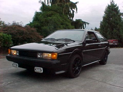
“8716”/
Photo
supermotors.net/registry/media/599372
VW Scirocco CIS Control Plunger Basic Measurement: Gland Nut Fig. 6-13 Manual Page

Reference · 1982-1988 SciroccoAll 1 manual pages

Service manual Figure 6-13 illustrating control plunger basic measurement at the gland nut and screw level.
Part of 1982-1988 Volkswagen Scirocco Manual Pages
This is a single illustrated figure from an automotive service manual, labeled Fig. 6-13. The line drawing shows a gland nut assembly viewed in perspective, with callout labels identifying the "Gland nut," a dimension point marked "a," and the "Screw level." The caption explains that the illustration depicts the control plunger basic measurement, which is measured at dimension "a," and notes that the gland nut and stop screw are shown with the control plunger omitted for clarity. The illustration carries the reference code B089GHV, a format typical of Bentley Publishers manual artwork. The figure teaches a reader where the basic setting measurement for a fuel-injection control plunger is taken, from the screw level inside the gland nut at dimension "a." No specific measurement values, torque specs, part numbers, or vehicle year/model applicability are stated on this page fragment; it serves purely as a visual reference for locating the measurement point during control plunger adjustment or inspection. The scan is a photograph of a printed manual page, cropped to show only this figure and its caption, with fragments of adjacent body text visible but unreadable along the right edge.
Is this accurate? Sign in to help verify it.
Frequently asked questions
- Where is the control plunger basic measurement taken?
- According to Fig. 6-13, the basic measurement is measured at dimension "a," at the screw level within the gland nut.
- What parts are shown in the Fig. 6-13 illustration?
- The figure shows the gland nut and stop screw; the control plunger itself is omitted for clarity.
- Does this page give an actual measurement value for dimension a?
- No. The figure only identifies where dimension "a" is measured; no numeric specification is visible on this page.
- What is the illustration reference code on this figure?
- The drawing carries the code B089GHV in its lower right corner.


No comments yet.