Home/
Registry/
Pontiac/
Grand Prix/
1997-2003/
1997 Pontiac Grand Prix/
Photo
supermotors.net/registry/media/756819
1997 Pontiac Grand Prix HVAC Air Delivery & Temperature Controls Wiring (C60)
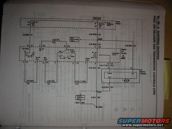
HVAC air delivery and temperature controls wiring diagram showing the fan switch, A/C control and color-coded circuits.
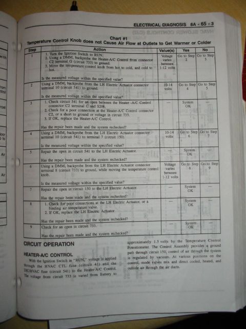
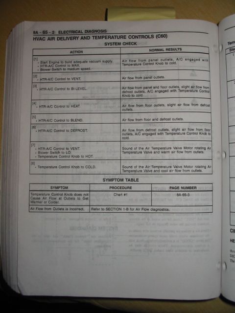
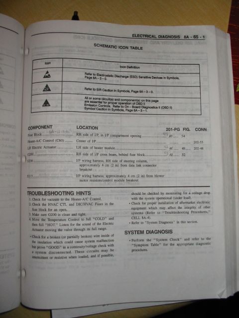
This document is a factory service manual wiring schematic, page 8A-65-0 "Electrical Diagnosis — HVAC Air Delivery and Temperature Controls (C60)." It shows the electrical circuit for the heater/A/C control head and blower fan switch. Power comes from the fuse block via the HVAC CTL fuse (20 A, cavities B3/B4) and the DIC/HVAC fuse (10 A, cavities B1/B2), with references to Power Distribution Cell 10 and Fuse Block Details Cell 11. Circuit 41 (0.8 BRN) feeds the fan switch, while circuit 541 (0.35 BRN) feeds the temperature control potentiometer and the LH electric actuator through splice S206. The diagram identifies the mode switch positions (Max, Vent, Bi-Level, Heat, Blend, Defrost) and their output circuits: 0.8 WHT 119, 0.35 YEL 271, 0.35 PPL 272, and 0.35 LT GRN 273. The temperature control signal 0.35 LT BLU 733 goes to pin 8 of the LH electric (blend door) actuator, which grounds through 0.35 BLK 150 to splice S213 and ground G200 (with 2 BLK 150 and 1 BLK 1450 circuits; see Ground Distribution Cell 14). A reader can trace wire colors, circuit numbers, connector pins, fuse ratings, splices, and grounds for HVAC control diagnosis.
Is this accurate? Sign in to help verify it.
Frequently asked questions
- Which fuses power the HVAC controls in this diagram?
- The HVAC CTL fuse rated 20 A (fuse block cavities B3/B4) and the DIC/HVAC fuse rated 10 A (cavities B1/B2), both fed from a 'Hot in Run' source in the fuse block.
- What wire feeds the blend door (LH electric) actuator control signal?
- A 0.35 LT BLU wire, circuit 733, runs from terminal G of connector C2 on the temperature control to pin 8 of the LH Electric Actuator.
- Where does the HVAC control circuit get its ground?
- Ground is through 0.35 BLK circuit 150 wires to splice S213, then via 2 BLK 150 (and 1 BLK 1450) to ground G200; see Ground Distribution Cell 14.
- What are the mode select output wire colors and circuit numbers?
- 0.8 WHT 119, 0.35 YEL 271, 0.35 PPL 272, and 0.35 LT GRN 273 (the LT GRN 273 wire is on the Defrost Mode output).
- What circuit powers the fan switch?
- A 0.8 BRN wire, circuit 41, from the 20 A HVAC CTL fuse feeds terminal B of connector C1 at the fan switch.
Comments
More from this build



No comments yet.