Home/
Registry/
Land Rover/
Discovery/
1999-2004/
“Britney”/
Photo
supermotors.net/registry/media/765503
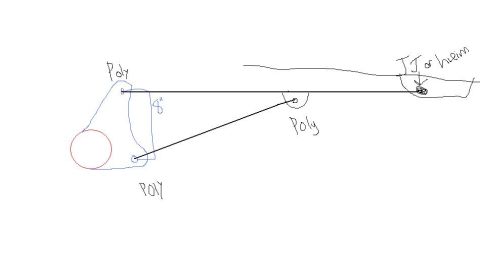
Radius Arm Link Setup Sketch - Poly Bushing & Heim/JJ Joint Layout, 8" Separation

Reference · 1999-2004 DiscoveryAll 1 schematics
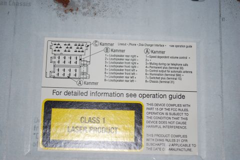
Rough hand-drawn serpentine belt and pulley routing sketch with labeled poly pulleys and a tensioner mark.
Part of 1999-2004 Land Rover Discovery Schematics
This is a simple freehand sketch (schematic) illustrating a proposed radius arm / link suspension setup, uploaded to the gallery of a 1999 Land Rover Discovery under the filename "ra setup.jpg". The drawing shows a red circle representing the axle tube with a blue bracket attached to it containing two link mounting holes spaced 8 inches apart vertically. Two links (drawn as black lines) run rearward from this bracket to the frame. The upper link attaches at the frame end with a joint labeled "JJ or heim" (i.e., a johnny joint or heim/rod-end style articulating joint), while all three other mounting points, the two bracket holes on the axle side and the frame-side mount of the lower diagonal link, are labeled "Poly," indicating polyurethane bushings. The only dimension given is the 8" vertical separation between the upper and lower link mounts on the axle bracket. The sketch contains no year, make, model, part numbers, torque specs, or other technical data; it serves purely as a conceptual layout for a link/radius-arm geometry showing joint type selection at each mounting location.
Is this accurate? Sign in to help verify it.
Frequently asked questions
- What joint types are shown at each mounting point in this radius arm setup sketch?
- Three mounting points are labeled "Poly" (the upper and lower holes on the axle-side bracket and the frame mount of the lower diagonal link), while the frame-side end of the upper link is labeled "JJ or heim."
- What is the spacing between the upper and lower link mounts on the axle bracket?
- The sketch notes an 8" separation between the two mounting holes on the axle-side bracket.
- How many links are shown in this setup?
- Two links are drawn: an upper link running straight back to the frame (ending in a JJ or heim joint) and a lower link running diagonally to a frame-side poly mount.
- Does the sketch provide any part numbers or torque specifications?
- No. The only information given is the joint types at each mount (poly, and JJ or heim) and the 8" mount spacing on the bracket.
No comments yet.