Hand-Drawn 24V Thermostat, Transformer, Relay & Fan Switch Wiring Diagram
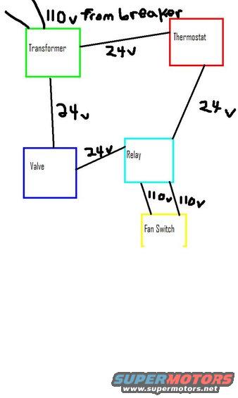
Wiring diagram of an HVAC-style control circuit linking transformer, thermostat, relay, valve and fan switch at 24V and 110V.
This is a simple hand-drawn wiring diagram (digital sketch) showing the low-voltage and line-voltage connections for what appears to be a heating/HVAC control circuit. Five labeled component boxes are shown: a Transformer (green box), Thermostat (red box), Valve (blue box), Relay (cyan box), and Fan Switch (yellow box). Two supply wires labeled '110v from breaker' feed the Transformer. The Transformer outputs 24v on two circuits: one 24v wire runs to the Thermostat and another 24v wire runs down to the Valve. The Thermostat connects via a 24v wire to the Relay, and the Valve also connects to the Relay via a 24v wire. From the Relay, two wires each labeled '110v' run to the Fan Switch. A reader can learn the basic control topology: household 110V power steps down through a transformer to a 24V control circuit that links the thermostat, valve, and relay, with the relay switching 110V power to the fan switch. No part numbers, wire colors (beyond box outline colors), fuse ratings, terminal designations, or applicability information (year/make/model) appear anywhere in the drawing.
Is this accurate? Sign in to help verify it.
Frequently asked questions
- What voltage feeds the transformer in this diagram?
- Two wires labeled '110v from breaker' supply the transformer.
- What voltage runs between the thermostat and the relay?
- A 24v wire connects the thermostat to the relay.
- How is the fan switch wired?
- Two wires, each labeled 110v, run from the relay to the fan switch.
- What components does the 24v side of the transformer feed?
- The transformer sends 24v to the thermostat and 24v to the valve; the thermostat and valve each connect to the relay with 24v wires.
Comments
More from this build










No comments yet.