Home/
Registry/
Ford/
Ranchero/
1977-1979/
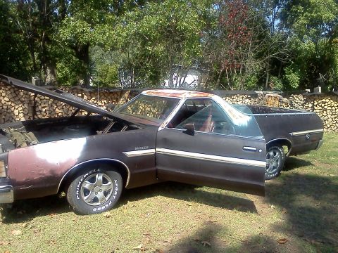
1979 Ford Ranchero/
Photo
supermotors.net/registry/media/926319

This diagram illustrates a suction throttling valve and includes a chart correlating altitude with required gauge readings.
36-32 SUCTlON THROTTLING VALVE REFRIGERANT FLOW CONNEtTpR LF J V ' P ATO" PROTECUQN EVA 0R R mun: CAP . j ' LgEcoNNEpTloN L 1 - pm sucriou PRESSURE) j REGULATED EVELORE 05. FREssuRETEST CpNNEgToR (CHARGmG VALVE) T0 COMPRESSOR SUCTlON PRESSURE FROM REGULATED EVAPORATOR PRESSURE PRESSURE DIFFERENTVAL VALVE (STARTS TO OPEN @10 P.S.l. FULLY OPENZU P.S.l.l NON-REGULA (COMPRESSOR S'JC 1 TTLE VALVE PRESSURE/ALTITUDE CHART SUCTION THRO ALTITUDE 0F TEsT SlTE 1FEET) REQUIRED GAUGE READING :1 p51 0 FEET (Sea Level] 23.5 1000 FEET 29.0 2000 FEET 295 3000 FEET 30.0 4000 FEET 30.5 5000 FEET 31.0 6000 FEET 31.4 7000 FEET 31.3 8000 FEET 32.3 9000 FEET 32.7 , 10,000 FEET 33.2 L L, L1720-c\. e Chart FIG. l0 Suction Throttling Valve and Pressure/Altitud tting adapters T71P-19703S and R REFRIGERANT SERVICE 7 After the system is nearly discharged, fold gauge low and high SCHARGMG THE SYSTEM 0n the mam Open the high pressure gauge valve When replacing any component inthe pressure hoses. very slowly to avoid losing an air conditioning system, the system must 4. Connect the high and low pressure excessive amount of refrigerant oil be discharged. T0 discharge the system gauge hoses with adapters, to the and allow any refrigerant remaining proceed as follows: respective high and low pressure in the compressor and high pressure line to discharge. ,~ 1, s from the high and charging valves (Fig. 11 or 12). 1. Remove the cap lOW charging valves in the high and 5. Place the open end of the center hose low pressure lines (Fig. 11 or 12). in a garage exhaust outlet. 2, Tum both manifold gauge valves fUlly 6. Slowly depressurize the refrigeration EVACUAHNG THE SYSTEM : system by opening the low pressure 11 Discharge the system as described in V " the preceding procedure. ge set to the Refrigerant12 and lve a slight amount and to the manifold clockwise to close the gau gauge va he refrigerant to discharge center outlet hoses. 3. If the gauge set hoses do not have the allowing t charging valve actuating pins, install slowly from the system. 2. Attach a tank of a vacuum pump
Comments
More from this build

No comments yet.