Home/
Registry/
Ford/
Bronco/
1992-1996/
1993 Ford Bronco/
Photo
supermotors.net/registry/media/927599
Document shows installation instructions for an adjustable fan control.
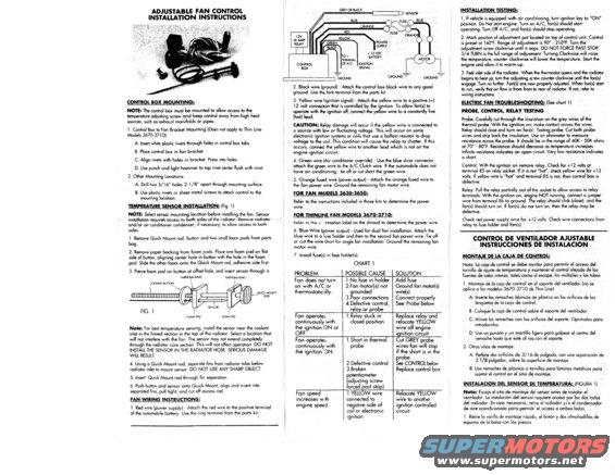
ADJUSTABLE FAN CONTROL INSTALLATION INSTRUCTIONS CONTROL BOX MOUNTING: NOTE: The control box must be mounted to allow access to the temperature adjusting screw and keep control away lrom high heat sources. such as exhaust monitolds or pipes. I. Control Box to Fun Bracket Mounting (Does not apply to Thin Line Models 367037l0): A. Insert white plastic rivets through holes in control box tabs. B. Place control box in ion bracket C. Align rivets with holes in bracket. Press Into holes. D. Use punch and light hammer to tap rivet center llush with rivet. 2, Other Mounting Locations: A. Drill two 3/16" holes 2-1/8" apart through mounting surface. B. Use plastic rivets or sheet metal screws to attach control to the mounting location. TEMPERATURE SENSOR INSTALLATION: (Fig. 1) NOTE: Select sensor mounting location belore installing the (on. Sensor installation requires access to both sides at the radiator Remove radiator and/or air conditioner condenser, it necessary, to allow access to both sides. l. Remove Quick Mount rod, button and two small team pads tram parts bag. 2. Remove paper backing tram loam pads. Place one team pad on (lot side at button, aligning center hole in button with the hole in the loam pad. Slide the other loam onto the Quick Mount rod, adhesive side tirst. 3. Pierce loam pad on button at oltset hole, and insert sensor through it. PAPER BACKING PAPER BACKING IOCKtNG sunon ( i ouicr MOUNT ' ROD SEN'lOIi no. I 1 f rom PAD ram no Note: For best temperature sensing, install the sensor near the coolant inlet in the tinned section in the top ol the radiator. Select a location that will not interfere with the ion. The sensor may not extend completely through the radiator core section. This will not allect operation. DO NOT INSTALL THE SENSOR lN THE RADIATOR HOSE. SERIOUS DAMAGE WlLL RESULT, 4 Using a Quick Mount rod, separate lins tram radiator tube below radiator inlet to mount sensor. DO NOT USE ANY SHARP OBJECT, 5. Insert Quick Mount rod through (in separation 6. Push button and sensor onto Quick Mount, align and insert into separated tins, pull tight, and cut all excess rod FAN WIRING INSTRUCTIONS: I. Red wire (power supply) . Attach the red ware to the positive terminal at the automobile battery, Use the ring terminal lrom the parts lrit GREY 0! BLACK 2. Black wire (ground) ~ Attach the control box black wire to any good ground. Use the lork terminal lrom the parts lrit. 3. Yellow wire (ignition signal) - Attach the yellow wire to a positive (+) I2 volt connectan that is controlled by the i nition. To allow tan(s) to operate with the ignition all, connect the yel ow wire to a constantly live (hot) lead. CAUTION: Relay damage will occur it the yellow wire is connected to a source with low or uctuating voltage. This will occur on some electronic i nition systems or coils that use a ballast resistor to drop voltage to tie (oil. This condition will cause the relay to chatter. It this occurs, conned the yellow wire to another lead which is not on the engine ignitior. circuit. A. Green wire (Air conditioner override) - Use the blue slicer connector, attach the great wire to the A/ C Clutch wire. It the automobile does not GROUNDT have air canditoning, tie all or cut short the green wire. 5. Orange lusetl wire (power output) - Attach the orange tused wire to the tan power wire. Ground the remaining tan motor wire. FOR FAN MODELS gag-3659: Reter to the instructions included in those kits to determine the power wire. FOR THINLINE FAN MODELS 3670-3710: Rater to the n. :rrnation label on the shroud to determine the power wire, 6. Blue Wire (power output) Used tor dual (an installation. Attach the blue wire to a iuse holder and then to the second tancpower wire. Tie oil or cut the wire short tor single lan installation. Groun motor wire. 7. Install tuse(s) in luse holder(s). PROBLEM CHART I POSSIBLE CAUSE the remaining lan SOLUTION INSTALLATION TESTING: I. It vehicle is equipped with air conditioning, turn ignition key to ON posrtion. Do Not start engine. Turn on A/C, tan(s) should start operating. Turn Oil A/ C, and tan(s) should stop operating. 2. Mark position at adjustment pot located on top at control unit, Control is reset at I60F. Range oi ad'ustment is 90 - 2I0F. Turn the arliustment screw clockwise until it stops. DO NOT FORCE PAST STOP. 3/4 TURN is the lull range at adjustment. Turning Clockwise will raise the temperature, counter clockwise will lower the temperature. Start the engine and allow it to warmrup. 3. Feel inlet side at the radiator. When the thermostat opens and the radiator begins to heat up, turn the adjusting screw counter clockwise until the tan(s) engage. Turn na turther. Fan(s) are now properly adjusted. When lanls) start to run, verily that air llow is (Tom front to rear a radiator. It not, reler to wiring instructions. ELECTRIC FAN TROUBLESHOOTING: (See chart I) PROBE, CONTROL, RELAY TESTING Probe: Carelully cut through the insu'otion on the grey wires at the thermal probe. With the ignition on, make contact across the wires Relay should close and turn on tanls, Testin probe: Cut both probe wires and strip back the insulation. Use an mmeter to measure resistance across the probe. It should be in the range at 40K - 50K ohms at 70 - 80F. Resistance should decrease as tern ature increases. Intijiite resistance indicates an open circuit. Very ow resistance indicates a 5 art. Control: With the ignition on remove relay. Check tor H 2 volts at terminal 85 on relay socket. It it is not "hot", check yellow wire for +I 2 volts. It yellow wire is "hot" and terminal 85 is not, then control box is detective. Relay: Pull the relay partially out at the socket to allow access to relay terminals. With the ignition on, engine NOT running, connect a jumper wire tram terminal 86 to ground. The relay should click (close). and the tan(s) should turn on. it tank) do no turn on, then the relay may be delective. Check red power supply wire tor +I2 volts. Check wire connections from relay to (use holder and ianls), Fan does not turn on with A/C or thermostatically. I.No tuse in holder ZFan motor(s) not grounded 3.Poor connections 4.Delective control, relay or probe Add Fuse Ground tan motor(s) wire(s) ( Connect proper y See Probe below Fan operates continuously with the ignition ON or FF. I.Relay stuck in closed position Replace relay and relocate YELLOW wire olt engine ignition circuit Fan operates continuously with the ignition ON. I .Short in thermal probe 2.Delective control 3.3roken tentiometer adjusting screw arced past stop) Cut GREY probe wires-tan will sto it the short is in e probe See CONTROL below Replace control box Fan speed increases w th engine speed. l .YELLOW wire connected to negative side at coi or electronic ignition Relocate YELLOW wire to another ignition controlled circuit CONTROL DE VENTILADOR AJUSTABLE INSTRUCCIONES DE INSTALACION MONTAJE n: M CAJA DE comma Nata: La caia de control se debe mentor para permitir el occeso del tornillo de ojuste de temperature y mantener el control aleiado de las Fuentes de calor intenso, tales como el escape, las multiples y los tubas l . Montaje de la caja de control en el soporte del ventilador (no se aplica a los modelos 36707371 0 de Thin Line) A. Inserte los remaches blancas rte plastico en los oriiicios de las lenguetas de la caia de control. B. Coloque Ia caja de control sobre el soporte del ventilador. C. Alinee las remaches con las oriticios del soparte. Oprimalos para introducirlas. D. Use an punzn y un martillo ligero para golpear el centro del remache hasta que est al ras con el soporte. 2. Otros sitios de montaje: A. Perlore dos arilicios de 3/I6 de pulgada, con uno separacion de 2 1/8 pulgadas, sobre la superhcie de montaie. B. Use remaches de plastico o tornillos para laminas metalicas para sujetar el control en el sitio de montaje. INSTALACION DEL SENSOR DE TEMPERATURA: (FIGURA I) Nola: Escoja el sitio de montaje del sensor antes de instalar el ventilodor. La instolacion del sensor requiere acceso por los dos lados del radiador. En caso necesario, retire el radiador y/o el condensador de aire acondicionado para permitir el acceso a ambos lados. i. Retire la varilla de montaje rapid), el baton y dos almohadillas de espuma de la balsa con las piezas.
Comments
More from this build


No comments yet.