Home/
Registry/
Chevrolet/
C/K Pickup/
1973-1987/
“RootBreaker”/
Photo
supermotors.net/registry/media/928513
Axial Axle Link & Driveshaft Install Diagram - Step 15 (AX80016, AXA867, AXA180)
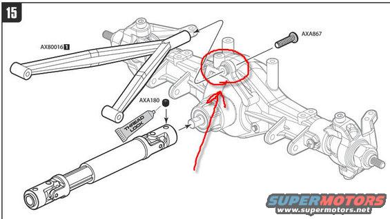
Exploded parts diagram of a driveshaft and front axle assembly with part-number callouts.
This document is step 15 of an assembly instruction sheet showing an exploded parts diagram. It depicts the installation of a suspension link (part AX80016, quantity marker 1) onto an axle housing, secured by a screw (part AXA867) that threads into a mounting boss on top of the axle, this attachment point is emphasized with a hand-drawn red circle and arrow, apparently added by the uploader to highlight the specific fastener location in question. The diagram also shows a telescoping driveshaft with a universal joint being inserted into the axle input shaft, along with a small part (AXA180) that receives thread lock, indicated by a 'THREAD LOCK' tube icon and an application arrow. A reader can learn the three part numbers used in this step (AX80016, AXA867, AXA180), the orientation and insertion direction of the driveshaft, where thread lock must be applied, and exactly which screw boss on the axle housing the link attaches to. The part number prefixes (AX/AXA) and drawing style indicate this is from an Axial R/C vehicle instruction manual rather than a full-size automotive service document; no year, model, or torque values are stated.
Is this accurate? Sign in to help verify it.
Frequently asked questions
- What part numbers are shown in this diagram?
- Three part numbers appear: AX80016 (link, marked with quantity 1), AXA867 (screw), and AXA180 (small part installed with thread lock).
- Where is thread lock required in this step?
- A 'THREAD LOCK' tube icon with an arrow points to part AXA180, indicating thread lock should be applied to it before installation.
- What does the red circle on the diagram highlight?
- A hand-drawn red circle and arrow mark the boss on top of the axle housing where the AXA867 screw and the AX80016 link attach.
- What assembly step does this page cover?
- It is step 15, covering installation of the AX80016 link onto the axle housing with the AXA867 screw, plus insertion of the telescoping universal-joint driveshaft into the axle input.
Comments
More from this build

No comments yet.