Home/
Registry/
Hyundai/
Genesis Coupe/
2010-2016/
“Coupe”/
Photo
supermotors.net/registry/media/943928
Diagrams show how to install a fan controller with a capillary t…

Fan ControllerView all 13
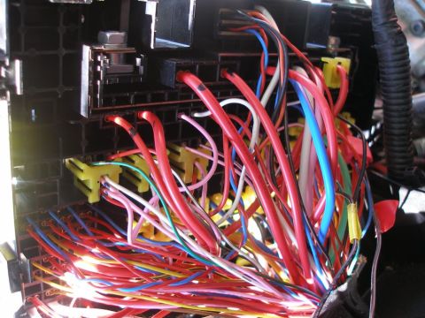
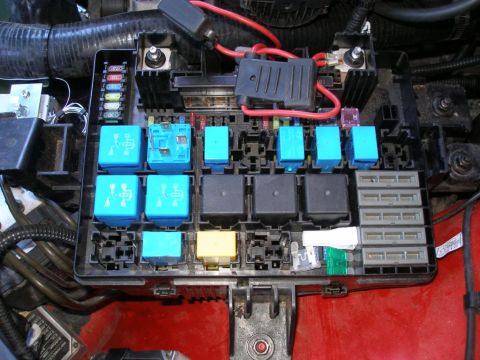
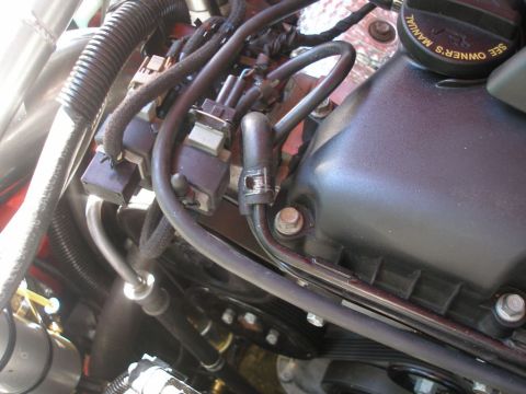
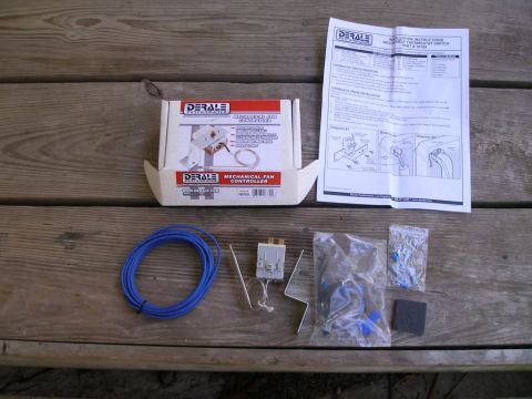
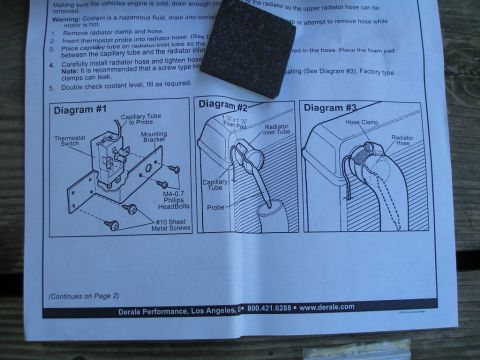
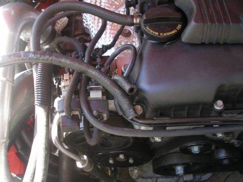
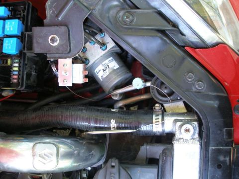
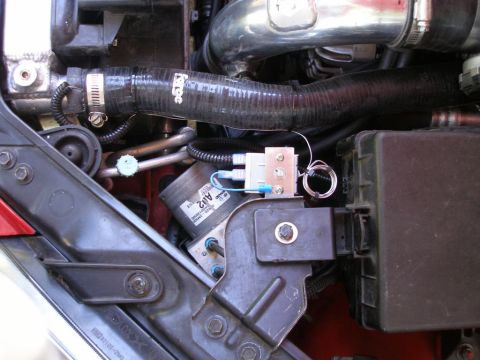
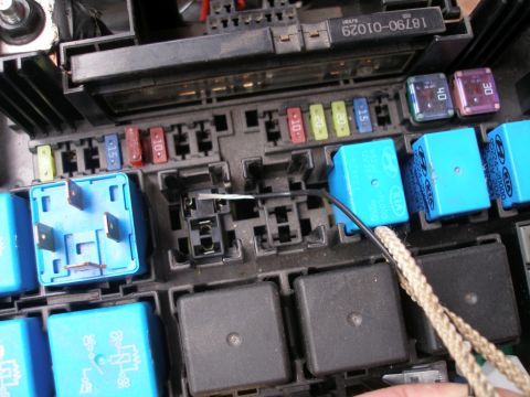
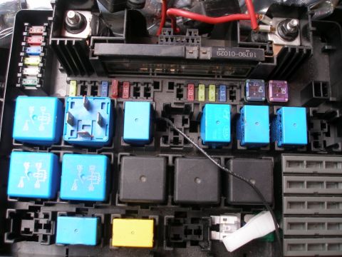
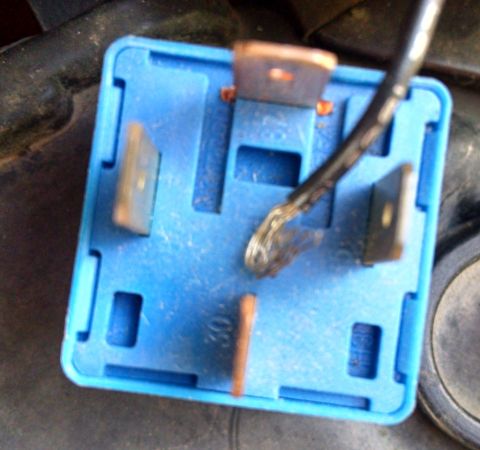
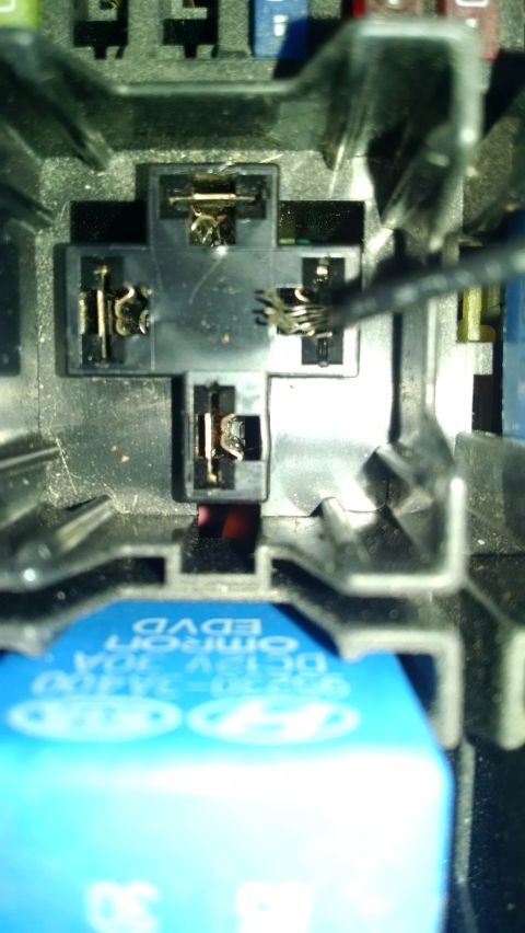
Installation instructions detail the placement of a thermostat switch and capillary tube for a fan controller system.
mixing the whales snglne .5 calm an em," Warning; Coolant s a halardous um dram We Can mmor vs not Roman, radiator clamp and mm 1":anmarmaslaxnmbemo ramamrhosa (see Place capumn/ me on mm, mm! lube su m between me capmary Mme and he yamamr ml m w W h K < . m um m mm M; A Carelully ms|aH ramamr hose and ngmen hos mm- H 5 recommended mat a screw lype n cramps can eak Dauble check Domam level, rm 5 me rad amr so "we upper mmahr mm w - m m aempl m mn'uvr v; 3 5 rammed Diagram #1 C III T n abi Munnhng Bracket mmmsm Swwch Pmli s Head ans 1M0 Shae! Meta Screws (Cont/nues an Page 2) a- 500421.523: - www.detale.cum Delale Performance. Los Angeles,
Is this accurate? Sign in to help verify it.

No comments yet.