Document page with text and diagrams of bicycle components
This document page contains text and diagrams related to bicycle parts.
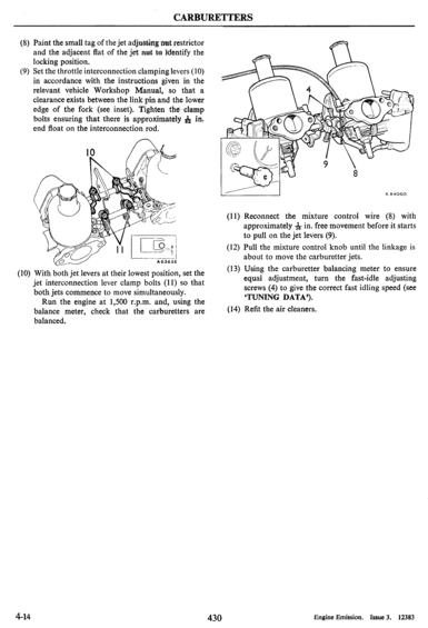
CARBURETTERS (8) Paint the small tag of the jet adjusting mat restrictor and the adjacent at of the jet; rmt to identify the locking position. Set the throttle interconnection clamping levers (10) in accordance with the instructions given in the relevant vehicle Workshop Manual, so that a clearance exists between the link pin and the lower edge of the fork (see inset). Tighten the clamp. bolts ensuring that there is approximately 312 in. end oat on the interconnection rod. (9) (10) With both jet levers at their lowest position, set the jet interconnection lever clamp bolts (11) so that both jets commence to move simultaneously. Run the engine at 1,500 r.p.m. and, using the balance meter, check that the carburetters are balanced. 4-14 430 Adoo (11) Reconnect the mixture control wire (8) with approximately 11; in. free movement before it starts to pull on the jet levers (9). (12) Pull the mixture control knob until the linkage is about to move the carburetter jets. (13) Using the carburetter balancing meter to ensure equal adjustment, turn the fast-idle adjusting screws (4) to give the correct fast idling speed (see TUNING DATA). (l4) Ret the air cleaners. Engine Emission. Issue 3. 12383
Is this accurate? Sign in to help verify it.
Comments
More from this build
No comments yet.