Home/
Registry/
BMW/
5 Series/
1997-2003/
“black betty”/
Photo
supermotors.net/registry/media/964890
BMW E39 5 Series IKE Cluster Module & Temperature Sensor Wiring Diagram (A63/B21)

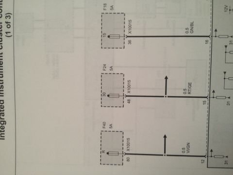
Wiring diagram showing the integrated instrument cluster control module circuits with color-coded wires, connector pins and a temperature sensor.
Part of 1997-2003 BMW 5 Series Wiring Diagrams
This document is a portion of a BMW wiring diagram (schematic style used in BMW electrical troubleshooting manuals) focused on the Integrated instrument cluster control module (IKE), designated A63, and its connection to the outside temperature sensor, designated B21. The diagram shows two module connectors: X10113 with pin 14 (0.35 mm² SW/GN wire) and pin 11 (0.5 mm² GE/BL wire), and X10114 with pins 24, 14, and 22. The B21 temperature sensor connects through connector X770: pin 2 of X770 runs via a 0.5 mm² BL/RT wire to pin 14 of X10114, and pin 1 of X770 runs via a 0.5 mm² BL/BR wire to pin 22 of X10114 on the IKE module. Internal module circuitry symbols show pull-up resistors, terminal 15 (switched power) and terminal 31 (ground) references, and a transistor output stage. A reader can learn the exact connector pin numbers, wire gauges, and German wire color codes (SW/GN = black/green, GE/BL = yellow/blue, BL/RT = blue/red, BL/BR = blue/brown) needed to test or trace the outside temperature sensor circuit to the instrument cluster module. The scan is rotated 90 degrees but the printed text is crisp and readable.
Is this accurate? Sign in to help verify it.
Frequently asked questions
- Which pins connect the temperature sensor to the IKE instrument cluster module?
- The B21 temperature sensor connects via connector X770: pin 2 goes through a 0.5 BL/RT wire to pin 14 of connector X10114 on the A63 IKE module, and pin 1 goes through a 0.5 BL/BR wire to pin 22 of X10114.
- What wire colors are used for the temperature sensor circuit?
- The signal wire is 0.5 BL/RT (blue/red) to X10114 pin 14, and the return wire is 0.5 BL/BR (blue/brown) to X10114 pin 22.
- What is component A63 in this diagram?
- A63 is the Integrated instrument cluster control module (IKE).
- What connector is used at the temperature sensor B21?
- Connector X770, using pin 2 (BL/RT wire) and pin 1 (BL/BR wire).
- What wire sizes and colors go to connector X10113 on the IKE module?
- Pin 14 uses a 0.35 SW/GN (black/green) wire and pin 11 uses a 0.5 GE/BL (yellow/blue) wire.
Comments
More from this build
No comments yet.