Home/
Registry/
Jeep/
Cherokee/
1984-2001/
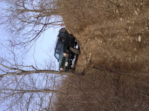
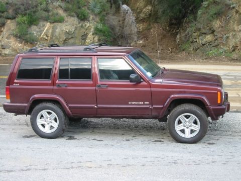
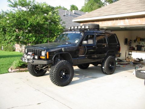
1994 Jeep Cherokee/
Photo
supermotors.net/registry/media/971138
Ford Mustang Locking Steering Column Exploded Diagram - Lock Cylinder & Switch

Exploded parts diagram of a steering column turn-signal and hazard switch assembly with labeled screws, snap rings, drive gear, and lock cylinder.
This document is a black-and-white exploded parts diagram of a locking steering column assembly, showing the components at the upper end of the column and how they fit together. The illustration identifies the turn signal switch with its three required mounting screws, the two T-bolt retaining nuts, the locking button snap retainer, the plastic cover, and the rod that connects to the ignition switch. Also labeled are the hazard warning switch, the snap ring retainer, the flange casting (the main column housing shown at the center of the drawing), and the wire loom exiting the column. The lower-right portion of the diagram details the ignition lock cylinder installation stack-up: drive gear, washer, snap ring, and two spring clips that retain the lock cylinder in the column. A separate mounting screw and the key warning buzzer terminal (attached by a wire lead to the hazard/turn signal area) are also called out. A reader can learn the names, order, and relative positions of all major serviceable parts in this style of locking steering column, which is useful when disassembling or reassembling the column, replacing a turn signal switch, or removing and installing the ignition lock cylinder. The diagram contains callout labels only; no part numbers, torque specifications, years, or model designations are printed on it.
Is this accurate? Sign in to help verify it.
Frequently asked questions
- How many mounting screws does the turn signal switch use?
- The diagram calls out three mounting screws required for the turn signal switch.
- What parts retain the ignition lock cylinder in the column?
- The diagram shows the lock cylinder retained with spring clips (two shown), along with a snap ring, washer, and drive gear in the assembly stack.
- How many T-bolt retaining nuts are required?
- Two T-bolt retaining nuts are required, per the diagram callout.
- Where does the actuator rod from the column go?
- The diagram labels a rod running from the column to the ignition switch ('ROD TO IGNITION SWITCH').
- Is the hazard warning switch shown in this diagram?
- Yes, the hazard warning switch is labeled on the turn signal switch assembly at the left of the diagram, along with a key warning buzzer terminal on a wire lead.
Comments
More from this build




No comments yet.