FW
Member profile
Fred Willson
391 photos
1 vehicle
member since 2001
Beacon, NY, U.S.A.
The garage · 1
Fred Willson’s vehicles on the registry.
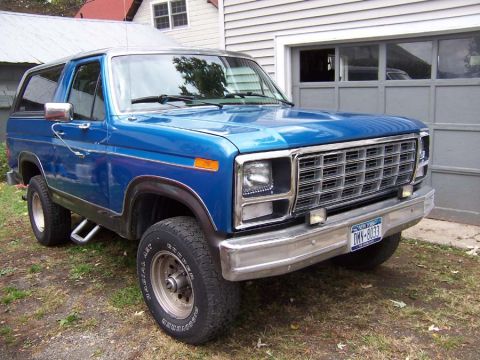
Latest photos
The newest 12 uploads from Fred Willson’s garage.