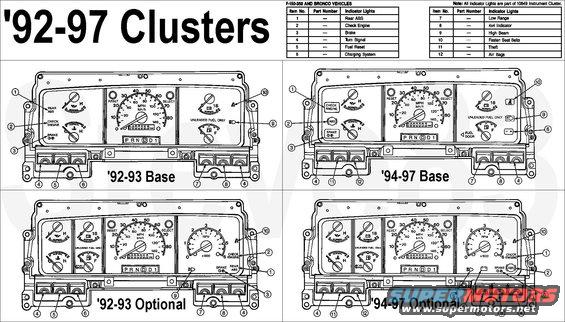
'92-97 Warning Indicators
IF THE IMAGE IS TOO SMALL, click it.
To access the cluster, see:

Other than the speedometer, '87-91 clusters & instruments are very similar.

Brake System

All vehicles use a brake warning light in the instrument cluster to warn of system malfunctions. The red warning light for the brakes can show three things -- that either the parking brake is not fully released, that the brake fluid level is low in the master cylinder reservoir or the vacuum pressure is low on diesel engine vehicles.

Anti-Lock Brakes, Bronco

The anti-lock brake system uses one amber ABS warning light to alert the driver of malfunctions in the system.
The amber ABS warning light will come on for numerous reasons. It warns the driver that the ABS has been disabled. Normal power-assisted braking remains but the wheels can lock during a panic stop while the indicator is on. Certain procedures must be followed to find the concern in this situation. Refer to Section 06-09B in the Powertrain/Drivetrain Manual for diagnosis and testing of the system.
Rear Anti-Lock Brakes, F and E Series

The yellow anti-lock brake indicator lights up for approximately two seconds when the ignition switch lock cylinder is first moved to ON or START for circuit prove out. The indicator also lights up when the RABS module detects a malfunction in the system.
The self-test feature contains codes that indicate the area of the malfunction. When a malfunction is detected, the RABS control module shuts down the system and the yellow anti-lock warning indicator comes on. This permits normal braking. A code can be retrieved by momentarily grounding the diagnostic pigtail (black with orange stripe wire) after it is disconnected from KAM (keep-alive power red wire) and counting the flashes of the yellow ABS lamp. To make sure the diagnostic trouble code (DTC) is not lost from memory, the ignition switch lock cylinder must be left in the ON position before the diagnostic lead is disconnected from KAM power. If more than one diagnostic trouble code exists, only the first code stored will be displayed. Additional codes will be output only after the first fault is corrected.
Check Engine

The check engine warning indicator comes on when the electronic engine control system is not working properly.
The check engine warning indicator comes on briefly when the ignition switch lock cylinder is turned to ON, and should turn off when the engine starts. If the check engine warning indicator does not come on when the ignition switch lock cylinder is turned to ON or if it comes on while the vehicle is moving, the system is malfunctioning.
NOTE:
If the vehicle is equipped with dual fuel tanks, the CHECK ENGINE light may come on if fuel is restricted to the engine or if the fuel flow is momentarily disrupted because of an empty fuel tank before switching to the auxiliary fuel tank. This condition is normal and the CHECK ENGINE light should go off sometime after fuel flow is restored.
Charging System

.

.

.

The charge indicator lights if the voltage in the integral generator drops below a preset level while the ignition switch lock cylinder is in RUN.
The charge indicator light comes on every time the ignition switch lock cylinder is turned to ON or START. The light should go off when the engine starts and the generator begins to charge.
Air Bag, (if Equipped)

The air bag warning indicator will illuminate for six seconds when the ignition switch lock cylinder is turned to the ON position. If the air bag warning indicator fails to illuminate, continues to flash, remains on, or if a series of five beeps is heard, the system requires service.
Safety Belt

The safety belt warning light reminds the driver to fasten safety belt. Each time the ignition switch lock cylinder is turned on, the warning light will come on for a short time to remind the driver to fasten the safety belt.
High Beam
The high beam indicator comes on when the headlamps are turned on high beam or when the headlamps are flashed.
LH/RH Turn Signals

The LH/RH turn signal indicators are located in the instrument cluster. If the turn signal indicator light in the instrument cluster does not illuminate or remains on (doesn't flash) when a turn is signaled, the turn signaling system is malfunctioning.
Overdrive/Overdrive Off

A transmission control switch and an indicator labeled OVERDRIVE is located on the end of the gearshaft lever. Press this switch and the word OFF will illuminate on the shift lever knob. With the word OFF illuminated, the transmission will operate in gears one through three. Operating in overdrive OFF gives more engine braking than overdrive and is useful for descending hills.
To return the transmission to the normal overdrive operation, press the transmission control switch again. The switch may be used to select overdrive or overdrive OFF at any time the vehicle is being driven.
If the transmission control indicator light is flashing on and off repeatedly, the transmission system is malfunctioning. The transmission will operate in a failure management mode with harsh engagements, firm shift feel, and abnormal shift schedule.
4x4 Low and High Range Indicators with Lever Operated Transfer Case

The 4x4 low and high lamp circuit consists of two indicator lamps located on the instrument cluster and a switch located in the transfer case. One lamp indicates when the vehicle is in the 4-wheel drive high range position (4H) and one lamp indicates when the vehicle is in the 4-wheel drive position (4L).
When the 4-wheel drive high range is engaged, the switch closes at first contact and the 4x4 HIGH RANGE lamp illuminates. When the low range is engaged, the switch closes a second contact and the low range bulb illuminates at the same time as the 4x4 LOW RANGE lamp illuminates.
4x4 Low and High Range Indicators with Touch Drive System (Electronic Shift-On-the-Fly, ESOF)

A 4x4 indicator light and a LOW RANGE indicator light are located at the lower right of the instrument cluster. In addition, two small amber lights are located near the Touch Drive buttons. The amber light to the left of the 4x4 button will light up at the same time as the 4x4 instrument cluster light. The amber light to the left of the LOW RANGE light will light up at the same time as the instrument cluster LOW RANGE light.
Anti-Theft, '94-95 Bronco F/E-150-250-350 Vehicles
The anti-theft protection system provides two types of vehicle protection. The first is designed to provide the vehicle with protection from unauthorized entry into the passenger compartment and engine compartment (hood opening). The second monitors the status of the ignition switch lock cylinder. If triggered, the system provides both audio and visual alarm signals and disables the starter circuit.
The system is controlled by an electronic module. When armed, unauthorized entry into the vehicle is detected by courtesy lamp switches (located in the passenger compartment door jambs), and a hood switch (located on the right cowl surface, E-series only). In addition, the system triggers an alarm if the ignition switch lock cylinder is forcibly removed from the steering column tube (3514).
NOTE:
The system immediately monitors the ignition switch lock cylinder upon removal of the key from the ignition.
Once triggered, the system flashes the low beam headlamps, the parking lamps, the alarm indicator lamp, and sounds the horn. In addition, the starter circuit is interrupted until the system is disarmed.
Fuel Filter, 7.3L Diesel
The 7.3L diesel engine is equipped with a fuel filter restriction sensor. A restriction indicator light is provided on the instrument panel (04320) to alert the operator.
If the restriction indicator light goes on during normal operation, the fuel filter should be changed as soon as practical.
Water in Fuel, 7.3L Diesel
During refueling it is possible for water-contaminated diesel fuel to be pumped into the fuel tank. The 7.3L diesel fuel system is equipped with a fuel filter/heater/water separator to remove water from the fuel. The WATER IN FUEL light will glow when the fuel filter/heater/water separator has a significant quantity of water, or when the key is switched to the START position (light function check). If the light glows red while the engine is running, the engine should be stopped as soon as safely possible, the engine shut off and the fuel filter bowl drained.
WARNING:
DO NOT DRAIN WATER SEPARATOR WHILE ENGINE IS RUNNING. FUEL MAY IGNITE IF SEPARATOR IS DRAINED WHILE ENGINE IS RUNNING OR VEHICLE IS MOVING. REFER TO OWNER GUIDE BOOKLET FOR WATER SEPARATOR DRAIN PROCEDURES.
CAUTION:
Allowing water to stay in the fuel system could result in extensive damage to, or failure of, the fuel injection system.
Inertia Fuel Shutoff Switch

.

If the engine cranks but does not start or does not start after a collision, the inertia fuel shutoff switch (9341) may be triggered. The inertia fuel shutoff switch is a device intended to automatically stop the flow of fuel to the engine when the vehicle has been involved in a collision. The impact does not have to be great for the inertia fuel shutoff switch to be triggered. Minor parking lot bumping and severe road impacts (such as potholes) may trigger the inertia fuel shutoff switch even when there is no apparent body damage.
WARNING:
IF YOU SEE OR SMELL FUEL, DO NOT RESET THE INERTIA FUEL SHUTOFF SWITCH OR TRY TO START THE VEHICLE. YOU COULD INJURE YOURSELF OR OTHERS. HAVE ALL PASSENGERS GET OUT OF THE VEHICLE AND CALL THE LOCAL FIRE DEPARTMENT OR A TOWING SERVICE.
Once the inertia fuel shutoff switch is triggered, the switch must be reset by hand before the vehicle can be started. Refer to the Owner Guide booklet for further explanation.
'92-93 trucks have an unused fuel reset indicator which can be made to work by swapping 2 wires in the IFS connector, and then adding some wiring & a bulb to the cluster. I'm working on a tech article to do that...
Wait To Start, 7.3L Diesel
With the key in the ON position, the WAIT TO START indicator will light if glow plug heat is necessary as a starting aid. The operator should wait until the light goes off before starting. If the indicator does not light, the engine may be started immediately. Refer to "Starting and Operating the Diesel Engine," in the Owner Guide booklet, for further explanation. After the engine starts, the indicator light will turn off.
The WAIT TO START light should always come on at least momentarily when the engine is cold and the key is first switched ON. If it does not, the glow plug system should be checked and repaired promptly to avoid difficult cold starting.
Instrument Cluster Printed Circuit
The instrument cluster printed circuit (10K843) which supplies current to the instrument panel indicators, gauges, and some clocks, is made of copper foil which is bonded to a polyester base film (usually referred to as Mylar �).
The instrument cluster printed circuit is mounted to the cluster housing and, due to its location, cannot be easily inspected or tested in the vehicle. This makes the instrument cluster printed circuit vulnerable to damage when a probe is used for in-vehicle testing as the probe can pierce the instrument cluster printed circuit or, in some cases, burn the copper conductor.
Since there is no approved procedure for in-vehicle testing of the instrument cluster printed circuit, it must be removed for visual inspection. If no visual damage is evident, each circuit should be tested with an ohmmeter. If an open circuit or short is detected, the instrument cluster printed circuit must be replaced.

Magnetic Gauges: Fuel, Engine Coolant Temperature, Battery Voltage and Oil Pressure
The magnetic gauge movement consists of three primary coils, one of which is wound at a 90-degree angle to the other two. The coils form a magnetic field which varies in direction according to the variable resistance of the sender unit (fuel and engine coolant temperature systems only; the oil pressure system uses a switch in place of sender and a fixed resistor on the instrument cluster printed circuit). A primary magnet, to which a shaft and pointer are attached, rotates to align to this primary field, resulting in pointer position. The bobbin/coil assembly is pressed into a metal housing which has two holes for dial mounting. There is no adjustment, calibration or maintenance required for these gauges.
NOTE: An instrument voltage regulator (IVR) is not required for this system. Refer to diagnostic procedure.
Fuel Level Indication System

The fuel level indicating system is a magnetic gauge system. It consists of a magnetic fuel gauge mounted in the instrument cluster and a fuel tank sending unit located in the fuel tank (9002). For Econoline and F-Series Motorhome Chassis only, an instrument cluster gauge amplifier (10E849) is in series between the two. No instrument voltage regulator is used with this system.
Fuel Gauge
The magnetic gauge movement consists of three primary coils, one of which is wound at a 90-degree angle to the other two. The coils form a magnetic field which varies in direction according to the variable resistance of the sender unit which is connected between two of them. A primary magnet, to which a shaft and pointer are attached, rotates to align to this primary field, resulting in pointer position. The bobbin/coil assembly is pressed into a metal housing which has two holes for dial mounting. There is no adjustment, calibration or maintenance required for these gauges.
Instrument Cluster Gauge Amplifier (Anti-Slosh Module)
The instrument cluster gauge amplifier provides a delay to the fuel gauge to prevent the fuel gauge pointer from fluctuating as a result of excessive movement in the fuel tank. The module is a small printed circuit board which latches into a pocket on the back of the instrument cluster. The electrical connections for ignition, ground, input from fuel sender and output to fuel gauge are made through a spring-type connector on the module to the instrument cluster gauge amplifier on the instrument cluster. There are no provisions for calibration or adjustment of the instrument cluster gauge amplifier.
Fuel Tank Sending Unit (EOUZ-9275-B '78-86 Bronco; PS22 / FOTZ-9A299-DB '90-96 Broncos)

The fuel tank sending unit consists of a variable screened resistor made up of a ceramic substrate. It is controlled by the action of an attached float in the fuel tank. When the fuel level is low, resistance in the fuel tank sending unit is low (~16 Ohms). When the fuel level is high, the resistance in the fuel tank sending unit is high (~160 Ohms). As the float moves from empty to full, the resistance will gradually and continuously increase.
The electric fuel delivery system is used on the 4.9L, 5.0L, 5.8L, and 7.5L Multiport Fuel Injection (MFI) engines and utilize a fuel delivery module (FDM) assembly. The FDM unit includes a high pressure fuel pump, venturi jet pump, supply check valve, and a shuttle selector valve all located internally in the module, which acts as a reservoir mounted from the fuel tank sending unit flange. The fuel tank sending unit attached to the reservoir body is a separately serviceable component.
In addition, the FDM system achieves a significant reduction in fuel system complexity and simplifies fuel line routing. The in-line fuel filter is located on the left-hand frame rail to provide service access.
The fuel tank sending unit (9275) for the 7.3L diesel also operates the same as previously described, except for the following differences. The sender electrical connector has two pins instead of four for F-Series and Bronco. Econoline uses a pigtail wire harness as there is no electric fuel pump. The venturi filter screen is replaced by an inverted flexible cone-like member. The flexible cone makes sure fuel is always being taken from the bottom of the fuel tank. The cone has as part of its assembly a relief-bypass valve. If the intake becomes obstructed at low temperatures the relief valve opens, allowing fuel to bypass the filter.
The fuel tank sending units used with all engines equipped with MFI, as well as the 7.3L diesel engine, have a fuel return port which allows excess fuel delivered to the engine to be returned to the fuel tank.
Fuel Tank Selector Switch (F-series w/dual tank only)
All fuel gauge sensing on vehicles with dual fuel tanks (except with 7.3L diesel engine (6007) passes through the fuel tank selector switch.
Engine Coolant Temperature Indication System
The engine coolant temperature indication system is a magnetic gauge system. It consists of a magnetic engine coolant temperature gauge mounted in the instrument cluster and an engine coolant temperature sender unit.
Engine Coolant Temperature Gauge
The engine coolant temperature gauge is a magnetic gauge movement consisting of three primary coils, one of which is wound at a 90-degree angle to the other two. The coils form a magnetic field which varies in direction according to the variable resistance of the engine coolant temperature sender unit. A primary magnet, to which a shaft and pointer are attached, rotates to align to this primary field, resulting in pointer position. The bobbin/coil assembly is pressed into a metal housing which has two holes for dial mounting. There is no adjustment, calibration or maintenance required for this gauge.
Engine Coolant Temperature Indicator Sender Unit (DOWY-10884-A)

When the engine coolant temperature is low, the resistance of the engine coolant temperature sender unit is high (74 Ohms), thus restricting the flow of current through the gauge, and moving the pointer only a short distance. As the coolant temperature increases, the resistance of the engine coolant temperature sender unit decreases (9.7 Ohms), causing a proportionately increased flow of current through the engine coolant temperature sender unit and a corresponding movement of the pointer.
The diesel engine's coolant temperature gauge uses an overheat switch that closes at approximately 116�C (240�F).
Oil Pressure Indication System

The oil pressure indication system consists of an oil pressure gauge and an oil pressure sender (9278 ).
Oil Pressure Gauge

The oil pressure gauge is a magnetic gauge movement consisting of three primary coils, one of which is wound at a 90-degree angle to the other two. The oil pressure system uses a switch and a fixed resistor; the resistor is attached to the engine wiring harness. A primary magnet, to which a shaft and pointer are attached, rotates to align this primary field, resulting in pointer position. The bobbin/coil assembly is pressed into a metal housing which has two holes for dial mounting. There are no adjustment calibrations or maintenance required for this gauge.
Oil Pressure Sender (EOAZ-9278-A)

The oil pressure sender (EOAZ-9278-A) controls the magnetic oil pressure gauge's pointer position. The oil pressure switch closes under normal engine operating conditions (above 6psi). The oil pressure switch opens with the engine off and no oil pressure (below 6psi).
Charge Indication System
With the ignition switch lock cylinder (11582) in START or RUN, the battery voltage gauge measures the vehicle's voltage to indicate the battery state of charge.
Battery Voltage Gauge
The battery voltage gauge is a gauge which measures the voltage potential at the battery to indicate the battery state of charge. The battery voltage gauge is a magnetic gauge which consists of three primary coils, one of which is wound at a 90-degree angle to the other two. The coils form a magnetic field which varies in direction according to the vehicle's voltage.
A primary magnet, to which a shaft and pointer are attached, rotates to align to this primary field, resulting in pointer position. The bobbin/coil assembly is pressed into a metal housing which has two holes for dial mounting. There is no maintenance required for this gauge.
Charging System Warning
With the ignition switch lock cylinder in START or RUN, battery voltage is present at the charge indicator. If the generator (GEN) (10346) is not generating power, the voltage regulator inside the generator grounds the charge indicator through circuit 904 (LG/R). The charge indicator illuminates.
When the generator is generating power, the voltage regulator inside the generator applies battery voltage to the charge indicator through circuit 904 (LG/R). With battery voltage present at both ends of the charge indicator, there is no current flow and the charge indicator does not illuminate.
Programmable Speedometer/Odometer Module (PSOM)

The programmable electric analog speedometer receives its input from the anti-lock brake sensor except on F-Super Duty Motorhome Chassis where it receives its input from the park brake-mounted speed sensor. The liquid crystal display (LCD) odometer is a combination trip odometer and total odometer. The total odometer is normally displayed. To see the trip odometer, press and release the SELECT button on the upper right side of the speedometer. To zero out the trip odometer, press and release the RESET button on the upper left side of the speedometer while the trip odometer is displayed. If the trip odometer is displayed, press and release the SELECT button to return the display to the total odometer value. The speedometer, containing the trip odometer and total mileage odometer, is serviceable only as an instrument cluster assembly.
NOTE:
Federal law requires that the odometer in any replacement speedometer must register the same mileage as that registered on the removed speedometer/odometer. Service replacement speedometer/odometer and odometer modules with the mileage preset to actual vehicle mileage are available through Ford Electronic Service Centers. In nearly all instances, the mileage continues to accumulate in the odometer memory even if the odometer does not display mileage. This mileage can usually be verified by the electronic service centers. Contact the service center for instructions to receive a replacement speedometer/odometer or odometer module with the mileage preset to actual mileage.
If the actual vehicle mileage cannot be verified, the service center will supply a speedometer/odometer module with the odometer display preset to zero ("0") miles and the service odometer segment ("s") illuminated in the vicinity of the odometer display. In addition, an odometer mileage sticker is supplied with the replacement odometer. This sticker must display the estimated vehicle mileage and is to be affixed to the driver's door.
NOTE:
Before ordering an instrument cluster, contact the instrument cluster technical hotline for diagnostic and system troubleshooting assistance. The hotline phone number is 1-800-523-7763.
The speedometer is also used to provide a speed signal for correct operation of the vehicle's powertrain control module (PCM) (12A650), transmission (7003), and speed control (if so equipped). Because of this, it is VERY IMPORTANT to change the speedometer's internal conversion constant if the size of tires on the vehicle is changed. Changing the conversion constant to the proper value when the tires are changed will also make sure that the speedometer retains the original factory-set accuracy. The conversion constant can only be changed six times once the vehicle leaves the factory. On F-Super Duty Motorhome Chassis the conversion constant must never be changed. If tires or rear axle ratio is changed, the gear in the park brake must be changed.
Odometer/Trip Odometer
The liquid crystal display (LCD) odometer is a combination trip odometer and total odometer. The total odometer is normally displayed. Press and release the SELECT button to see the trip odometer. To zero out the trip odometer, press and release the "reset" button. If the trip odometer is displayed, press and release the SELECT button to return the display to the total odometer value.
Tachometer (if Equipped)
The tachometer (17360) is an electrically operated gauge that indicates engine speed in rpm. In vehicles with gasoline engines, the tachometer receives its voltage pulses from the ignition coil when the engine is running. For 6-cylinder engines, the 8 terminal on the tachometer is left unconnected in the harness (open circuit); for 8-cylinder engines, the circuit is grounded. In vehicles with diesel engines, the engine's speed is indicated by the engine rpm sensor.

'93 Lightning tach F3TZ-17360-F
'94-95 Lightning tach F4TZ-17360-D
Transmission Range Selector Indicator ("Prindle" or "PRNDL")
The transmission range selector indicator is located below the speedometer for vehicles with automatic transmissions. A transmission control selector indicator opening cover (7B100) fills the window for manual transmissions. Early ('92-93) indicator cable guide tubes are white and very fragile; later tubes are black with visible bulges for the reinforcement strands. All attach to a plastic bracket on the steering column by a threaded adjusting wheel, and to a peg on the shift lever by an eye at the end of the cable.