EEC-IV DLC VIP test connector wiring diagram with pinout table f…
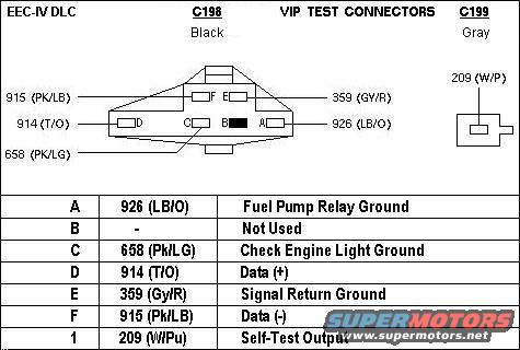
Diagnostic Link Connectors for EEC-IV processors ('84-95).
'84-86 (red) located on R wheelwell near starter relay.
'87-95 (black or gray) located under L hood hinge under EEC TEST cover. (WPT-743 & WPT-352)
'94-96 Bronco - do not confuse with RED 4WABS connector also under L hood hinge
'96-up use OBD-II, and this DLC: .
. 
Connect FP Relay (terminal A) to any ground (like terminal E) to force the fuel pump(s) on when the key is in RUN. .
. .
. 
Pins D & F are a primitive SCP bus, but on these old vehicles, nothing else was networked in.
After warming up the engine, connect pin 1 (209 W/Pu) to any ground (like terminal E) with any jumper wire (like a paperclip) to trigger diagnostic modes. (See the NEXT diagram.) Consult the 7th post on this page or scroll down here for the compete procedure to pull codes & trigger all test modes. If the CEL is burned out, connect CEL (C) to a 12V test light, and the light's other terminal to a positive 12V source on the same vehicle.
To hardwire a self-test switch in the dash, see:
Test sensors and actuators before disturbing them or their wiring.
Automotive Terms & Abbreviations
EEC-IV DTC definition list
No matter what code you get, DON'T PICK THE NAME OF A PART OUT of the code definition - read the WHOLE definition, and then confirm the condition it indicates. If the condition doesn't exist, clear the code and see how long it takes to re-set that code. If the condition DOES exist, learn about the system to identify EVERY possible cause of the condition. For example: if the EVP doesn't indicate the EGR is opening, that doesn't mean to replace either of them. It could simply be a vacuum leak in one of the lines, or the reservoir. No EEC can output both 2-digit AND 3-digit codes, so if you read them that way, you're reading them wrong. Aftermarket scantools for Ford EEC-IV are notorious for delivering nonexistent codes, so don't waste your time or money on them. A jumper wire will always produce usable results.
If spurious or false codes are delivered (codes whose indicated conditions DON'T exist), remove the EEC & inspect its PC board for leaking capacitors.
For voltage faults &/or contradictory faults, repair the battery terminals first:
Conditions: o = Key On Engine Off (KOEO), r = Engine Running (KOER), c = Continuous Memory
NO CODES Unable to initiate Self-Test or unable to output Self-Test codes (replace MIL bulb, inspect PC board inside EEC, read TSB below)
---------2-digit codes used until 1991---------
11 orc System PASS
12 -r- Cannot control rpm during Self-Test high rpm check
13 -r- Cannot control rpm during Self-Test low rpm check
14 --c PIP circuit failure (gas); tach sensor failure (diesel)
15 o-- EEC processor Read Only Memory (ROM) test failed
15 --c EEC processor Keep Alive Memory (KAM) test failed
18 -r- SPOUT circuit open
18 --c Loss of IDM input to processor/SPOUT circuit grounded
19 o-- Failure in EEC processor internal voltage
21 or- Engine Cooling Temperature (ECT) sensor out of Self-Test range (engine not warmed up before test)
22 orc Manifold Absolute Pressure (MAP) sensor out of Self-Test range
23 orc Throttle Position (TP) sensor out of Self-Test range
24 or- Air Charge Temperature (ACT) sensor out of Self-Test range
25 -r- Knock not sensed during Dynamic Response Test (operator error)
26 or- Transmission Fluid Temp (TFT) out of Self-Test range (engine not warmed up before test)
29 --c Insufficient Vehicle Speed Signal (VSS) input
31 orc EVP circuit below minimum voltage
32 orc EVP voltage below closed limit
33 -rc EGR valve opening not detected (no change in EVP when EVR activated)
34 orc EVP voltage above closed limit
35 orc EVP circuit above maximum voltage
41 -r- HEGO sensor circuit indicates system lean
41 --c No HEGO switching detected
42 -r- HEGO sensor circuit indicates system rich
43 --c Throttle Position (TP) sensor below idle spec
44 -r- Thermactor air system inoperative (TAB or TAD open circuit)
45 -r- Thermactor air upstream/misdirected during KOER
46 -r- Thermactor air not bypassed during KOER
47 o-- 4x4 switch closed during test (operator error)
49 --c 1-2 Shift error
51 o-c ECT indicated -40%uFFFDC (-40%uFFFDF)/circuit open
52 o-- Power Steering Pressure Switch (PSPS) circuit open
52 -r- PSPS circuit did not change states during Dynamic Response Test (operator error)
53 o-c TP above maximum voltage
54 o-c ACT indicated -40%uFFFDC (-40%uFFFDF)/circuit open
56 o-c Transmission Fluid Temp (TFT) indicated -40%uFFFDC (-40%uFFFDF)/circuit open
59 --c 2-3 Shift error
61 o-c ECT indicated 123%uFFFDC (254%uFFFDF)/circuit grounded
62 --c Torque Converter Clutch error
63 o-c TP circuit below minimum voltage
64 o-c ACT indicated 123%uFFFDC (254%uFFFDF)/circuit grounded
65 -r- Transmission Control Switch (TCS) circuit did not change states during Dynamic Response Test (operator error)
66 o-c Transmission Fluid Temp (TFT) indicated 143%uFFFDC (290%uFFFDF)/circuit grounded
67 o-- Neutral Drive Switch (NDS) circuit open; A/C or Defrost on (Manual) during test (operator error)
68 --c Transmission Fluid Temp (TFT) transmission over temp (over-heated)
69 --c 3-4 Shift error
72 -r- Insufficient MAP change during Dynamic Response Test (operator error)
73 -r- Insufficient TP change during Dynamic Response Test (operator error)
74 -rc Brake On/Off (BOO) circuit open or not actuated during Self-Test (operator error)
77 -r- Operator error during Dynamic Response Test
81 o-- Air Management 2 (AM2/TAD) circuit failure
82 o-- Air Management 1 (AM1/TAB) circuit failure
84 o-- EGR Vacuum Regulator (EVR) circuit failure
85 o-- Canister Purge (CANP) circuit failure
87 o-c Primary fuel pump circuit failure
91 o-- Shift Solenoid 1 (SS1) circuit failure
92 o-- Shift Solenoid 2 (SS2) circuit failure
93 o-- Coast Clutch Solenoid (CCS) circuit failure
94 o-- Torque Converter Clutch (TCC) solenoid circuit failure
95 o-c Fuel Pump circuit open - EEC processor to motor ground (fuel pump unplugged or wiring damage)
96 o-c Fuel Pump circuit open - battery to EEC processor (inertia switch tripped or FP relay failed)
97 o-- Transmission Control Indicator Lamp (TCIL) circuit failure
98 -r- Hard fault present
99 o-c Electronic Pressure Control (EPC) circuit failure
2-digit codes------------1991------------3-digit codes .
. 
111 orc System PASS
112 oc ACT indicated 123C (254°F)/circuit grounded
113 oc ACT indicated -40C (-40°F)/circuit open
114 or Air Charge Temperature (ACT) Sensor out of Self-Test range
116 or Engine Cooling Temperature (ECT) Sensor out of Self-Test range (engine not warmed up before test)
117 oc ECT indicated 123C (254°F)/circuit grounded
118 oc ECT indicated -40C (-40°F)/circuit open
121 orc Throttle Position (TP) Sensor out of Self-Test range
121 rc Throttle position voltage inconsistent with MAF sensor (vacuum leak downstream of MAF)
122 oc TP circuit below minimum voltage
123 oc TP above maximum voltage
124 rc Throttle Position (TP) sensor voltage higher than expected
125 rc Throttle Position (TP) sensor voltage lower than expected
126 orc Manifold Absolute Pressure (MAP) Sensor out of Self-Test range
128 c MAP vacuum circuit failure
129 r Insufficient MAP change during Dynamic Response Test (operator error)
136 c System indicates lean (Bank #2)
137 r System indicates lean (Bank #2)
157 orc Mass Air Flow (MAF) sensor circuit below minimum voltage
158 orc Mass Air Flow (MAF) sensor circuit above maximum voltage
159 orc Mass Air Flow (MAF) sensor circuit voltage higher or lower than expected
167 r Insufficient TP change during Dynamic Response Test (operator error)
171 c Fuel system at adaptive limits, Oxygen Sensor (HEGO) unable to switch, Bank 1
172 rc Lack of Oxygen Sensor (HEGO) switches, indicates lean, Bank 1
173 rc Lack of Oxygen Sensor (HEGO) switches, indicates rich, Bank 1
175 c Fuel system at adaptive limits, Oxygen Sensor (HEGO) unable to switch, Bank 2
176 rc Lack of Oxygen Sensor (HEGO) switches, indicates lean, Bank 2
177 rc Lack of Oxygen Sensor (HEGO) switches, indicates rich, Bank 2
179 c Fuel system at lean adaptive limit at part throttle, system rich, Bank 1
181 c Fuel system at rich adaptive limit at part throttle, system lean, Bank 1
184 orc Mass Air Flow (MAF) sensor voltage higher than expected
185 orc Mass Air Flow (MAF) sensor voltage lower than expected
186 orc Injector pulsewidth higher than expected (with BARO/MAP sensor)
186 orc Injector pulsewidth higher or mass air flow lower than expected (without BARO/MAP sensor)
187 orc Injector pulsewidth lower than expected (with BARO/MAP sensor)
187 orc Injector pulsewidth lower or mass air flow higher than expected (without BARO/MAP sensor)
188 c Fuel system at lean adaptive limit at part throttle, system rich (Bank #2)
189 c Fuel system at rich adaptive limit at part throttle, system lean (Bank #2)
211 c PIP circuit failure
212 c Loss of IDM input to processor/SPOUT circuit grounded
213 r SPOUT circuit open
214 orc Cylinder Identification (CID/CPS) circuit failure
215 orc PCM detected coil 1 primary circuit failure (EI/EDIS)
216 orc PCM detected coil 2 primary circuit failure (EI/EDIS)
217 orc PCM detected coil 3 primary circuit failure (EI/EDIS)
218 orc Loss of Ignition Diagnostic Monitor (IDM) signal-left side (dual plug EI/EDIS)
222 orc Loss of Ignition Diagnostic Monitor (IDM) signal-right side (dual plug EI/EDIS)
223 orc Loss of Dual Plug Inhibit (DPI) control (dual plug EI/EDIS)
224 orc PCM detected coil 1, 2, 3 or 4 primary circuit failure (dual plug EI/EDIS)
225 r Knock not sensed during Dynamic Response Test (operator error)
226 orc Ignition Diagnostic Monitor (IDM) signal not received (EI/EDIS)
232 orc PCM detected coil 1, 2, 3 or 4 primary circuit failure (EI/EDIS)
311 r Thermactor air system inoperative (Bank #1 w/dual HO2S)
312 r Thermactor air upstream/misdirected
313 r Thermactor air not bypassed
327 orc EVP circuit below minimum voltage
328 orc EVP voltage below closed limit
332 rc EGR valve opening not detected
334 orc EVP voltage above closed limit
334 orc EVP closed voltage higher than expected
335 o EGR (PFE) sensor voltage higher or lower than expected
336 orc Exhaust pressure high; PFE/DPFE circuit voltage higher than expected
337 orc EGR (EVP/PFE) circuit above maximum voltage
341 orc Octane adjust service pin open
411 r Cannot control rpm during low rpm check
412 r Cannot control rpm during high rpm check
452 c Insufficient Vehicle Speed Signal (VSS) input
511 o EEC processor Read Only Memory (ROM) test failed
512 c EEC processor Keep Alive Memory (KAM) test failed
513 o Failure in EEC processor internal voltage
519 o Power Steering Pressure (PSP) switch circuit open
521 r Power Steering Pressure (PSP) switch circuit did not change states (operator error)
522 o Vehicle not in PARK or NEUTRAL during KOEO test (operator error)
528 c Clutch switch circuit failure
536 r Brake On/Off (BOO) circuit failure/not actuated during Dynamic Response Test (operator error)
538 r Insufficient RPM change during Dynamic Response Test (operator error)
538 r (SFI engines only) Invalid cylinder balance test due to throttle movement during test (operator error)
538 r (SFI engines only) Invalid cylinder balance test due to CID circuit failure
539 or A/C on/Defrost on during test (operator error)
542 oc Fuel Pump circuit open - EEC processor to pump motor (no ground with FP relay OFF)
543 oc Fuel Pump circuit open - battery to EEC processor (no power with FP relay ON)
551 o Idle Air Control (IAC) circuit failure
552 o Air Management 1 (AM1/TAB) circuit failure
553 o Air Management 2 (AM2/TAD) circuit failure
556 oc Primary fuel pump circuit failure
558 o EGR Vacuum Regulator (EVR) circuit failure
565 o Canister Purge (CANP) circuit failure
566 o 3-4 shift solenoid circuit failure (A4LD)
569 orc Auxiliary Canister Purge (AUX-CANP) circuit failure
617 orc 1-2 shift error
618 orc 2-3 shift error
619 orc 3-4 shift error
621 o Shift Solenoid 1 (SS1) circuit failure
622 o Shift Solenoid 2 (SS2) circuit failure
624 orc Electronic Pressure Control (EPC) circuit failure
625 orc Electronic Pressure Control (EPC) driver open in PCM
626 o Coast Clutch Solenoid (CCS) circuit failure
628 rc Excessive converter clutch slippage
629 o Torque Converter Clutch (TCC) solenoid circuit failure
631 orc Transmission Control Indicator Lamp (TCIL) circuit failure
632 r Transmission Control Switch (TCS) circuit did not change states (operator error)
633 o 4x4L (Low) switch closed (operator error)
634 orc Transmission Range (TR) voltage higher or lower than expected
636 orc Transmission Fluid Temp (TFT) higher or lower than expected
637 orc Transmission Fluid Temp (TFT) sensor circuit above maximum voltage/-40°F indicated
638 orc Transmission Fluid Temp (TFT) sensor circuit below minimum voltage/290°F indicated
639 c Insufficient input from Transmission Speed Sensor (TSS)
641 o Shift Solenoid 3 (SS3) circuit failure
643 o Coast Clutch Solenoid (CCS) circuit failure
652 orc Torque Converter Clutch (TCC) solenoid circuit failure
654 or Transmission Range (TR) sensor indicating not in PARK during Self-Test (operator error or MLPS failed or shift linkage out of adjustment)
655 or Transmission Range (TR) sensor indicating not in NEUTRAL during Self-Test (operator error or MLPS failed or shift linkage out of adjustment)
656 c Torque Converter Clutch slippage error
657 orc Transmission Fluid Temperature (TFT) over temperature
667 orc Transmission Range (TR) circuit voltage below minimum voltage
668 orc Transmission Range (TR) circuit voltage above maximum voltage
691 orc 4X4 Low switch open or short circuit
692 rc Transmission state does not match calculated ratio
998 r Hard fault present, FMEM mode
NO CODES Unable to initiate Self-Test or unable to output Self-Test codes (replace MIL bulb, inspect PC board inside EEC, read TSB below)
Automotive Terms & Abbreviations
__________________________________________
TSB 92-24-03 Explanation of 3-Digit Codes & MIL
Publication Date: NOVEMBER 18, 1992
FORD: 1991-93 CROWN VICTORIA, ESCORT, MUSTANG, PROBE, TAURUS, TEMPO, THUNDERBIRD
LINCOLN-MERCURY: 1991-92 MARK VII
1991-93 CONTINENTAL, COUGAR, GRAND MARQUIS, SABLE, TOPAZ, TOWN CAR, TRACER
1993 MARK VIII
LIGHT TRUCK: 1991-93 AEROSTAR, BRONCO, ECONOLINE, EXPLORER, F SUPER DUTY, F-150-350 SERIES, RANGER
ISSUE: Occasionally, there are reports of the Malfunction Indicator Lamp (MIL) "Check Engine" Lamp (CEL) or "Service Engine Soon" (SES) lamp being lit with no Self-Test codes in Continuous Memory. An explanation of three digit EEC IV Self-Test Codes has been developed along with reasons for the MIL lamp being lit with no accompanying Continuous Memory Self-Test codes.
ACTION: Refer to the following explanation of three digit EEC IV Self Test Codes to determine why the MIL lamp is sometimes lit with no accompanying Continuous Memory Self-Test codes.
OVERVIEW OF THREE DIGIT EEC IV SELF-TEST CODES
Ford went from two digit to three digit EEC IV Self-Test codes in 1991 to service the increasing number of service codes required to support various government On-Board Diagnostic (OBD) regulations. The phase-in from two digit to three digit codes started in the 1991 model year and is largely complete except for some medium/heavy trucks that will retain two digit codes through the 1994 model year.
MIL LAMP ACTIVATION
Following is a list of reasons why a technician may see the MIL lamp lit with no accompanying Continuous Memory Self-Test codes.
1) Technician Not Familiar With Self-Test Code Output
There are two types of EEC Self-Tests, Key On Engine Off (KOEO) and Key On Engine Running (KOER). While both of these will test for various "hard faults" that are present when the test is run, the processor continuously monitors various operating parameters whenever the engine is running. If the processor detects a problem, it will store a "Continuous Memory" code and light the MIL. These Continuous Memory codes are put out during KOEO Self-Test after any codes associated with hard faults are output.
Self-Test Codes are displayed by flashing the MIL. They are also output as voltage pulses on the Self-Test Output (STO) circuit in the Self-Test connector. In either Self-Test mode, all codes are output twice and in KOEO, the hard fault codes are separated from the Continuous Memory codes by a "separator" pulse.
A technician that is unfamiliar with the EEC Self-Test can mistakenly believe that continuous Memory codes are not present when they really are. He may run KOER Self-Test and get a pass code (lll) and not realize that KOEO Self-Test must be run to receive any Continuous Memory codes. He may run KOEO Self-Test while counting MIL flashes and misinterpret the repeated hard fault pass code (lll) to mean that Continuous Memory does not contain any codes.
2) Inadvertent Erasure Of Continuous Memory Self-Test Codes
Continuous Memory Self-Test codes are erased by ungrounding STI before KOEO Self-Test is complete and all KOEO and Continuous Memory codes have been displayed. It is possible to inadvertently erase Continuous Memory codes by ungrounding STI without realizing that KOEO Self-Test is not complete or the processor has not finished displaying all the codes.
The EEC Self-Test codes are not only used by service technicians, they are used as a final system test in the assembly plants. To make this test as efficient as possible, Self-Test codes are output as a very fast, short pulsewidth signal before the codes are displayed by the flashing MIL. These "FAST" codes can only be interpreted by end-of-line equipment or code-reading testers like Ford's Self-Test Automatic Readout (STAR) testers.
The EEC IV processor puts out both 2-digit and 3-digit Self-Test codes in both formats, "FAST" pulsewidth mode and "SLOW" pulsewidth mode. While all "STAR" type testers display 2-digit codes, the original STAR tester cannot display 3-digit service codes. If the STAR tester is used on 3-digit service code applications, the display will be blank but the tester will beep. The beeps can be counted to determine service codes. The SUPER STAR II tester will only display 3-digit service codes in "FAST" code mode. If slow code mode is used on 3-digit service code applications, the display will be blank but the tester will beep. The beeps can be counted to determine service codes. For more information on running Self-Test, refer to the "EEC IV Quick Test Procedures and Appendix" section of the Powertrain Control/Emissions Diagnosis Service Manual.
Since certain STAR testers are capable of reading and displaying fast codes before the slow codes are finished being output on the MIL, a technician can assume that since he sees codes displayed, he can unground STI and move on. If he ungrounds STI before all slow codes are output, Continuous Memory will be erased and could put out a pass code (ll/lll) the next time KOEO Self-Test is run. The technician may also realize that his tester is in "SLOW" mode after he has initiated the KOEO test and stop the test to change tester settings. Another possibility is that another person, a vehicle owner or another technician, could have erased the codes before the technician reporting the situation has run Self-Test. In any of these situations, the vehicle must be driven until the Continuous Memory codes are reset.
3) The Concern That Set The Continuous Memory Code Is No Longer Present
The EEC processor will erase a Continuous Memory code if the concern that caused it has not been present for 40 or 80 warm-up cycles, depending on the vehicle. A warm-up cycle occurs when the vehicle is started with the coolant temperature below 120° F (49C) and then shutdown with the coolant temperature above 150°F (66C). If a vehicle is brought in for service with a MIL complaint and the vehicle is driven or otherwise allowed to warm-up before Self-Test is run, the code may be cleared before the technician tests it.
4) Grounded STO/MIL Circuit
The processor controls the MIL by grounding the STO/MIL circuit (Pin 17). If this circuit shorts to ground, whether the processor is controlling it or not, the MIL will be lit. Starting in 1991, if the processor has lit the MIL, it will hold it on for a minimum of 10 seconds. If the MIL flashes quickly, the concern is probably the STO/MIL circuit shorting intermittently to ground.
5) Engine Running In HLOS
The EEC processor will enter Hardware Limited Operation Strategy (HLOS) if it detects a problem that could cause further damage to the system. Under HLOS, the processor modifies its operating strategy so that certain functions are disabled but the vehicle can be safely driven in for service. If the vehicle is in HLOS, Continuous Memory codes will not be set and Self-Test cannot be initiated. However, Continuous codes that were set before the processor entered HLOS will be retained.
6) Misinterpretation Of MIL Bulb Check
The MIL will light as a bulb check if the key is on and the engine is not running. If the engine is running and stalls or stops for any reason with the key on, the MIL will be lit and no Continuous Memory codes will be set. When the key is first turned on, the MIL will stay lit briefly after the engine is started as part of the bulb check feature.
7) MIL Flashes During Self-Test
The circuit that controls the MIL is also the Self-Test Output (STO) circuit that goes to the Self-Test connector. The MIL will flash during Self-Test as the STO circuit is cycled on and off. This is normal and no Continuous codes are set.
8 ) Processor KAM Is Erased Or Fails
The Keep Alive Memory (KAM) within the processor must always have voltage supplied to it. This voltage is supplied by the Keep Alive Power (KAPWR) circuit (Pin 1) that connects directly to the battery. KAM contains adaptive parameter tables that allow the processor to adapt to different operating requirements. It also contains the Continuous Memory codes. Continuous Memory codes will be erased any time KAPWR is disconnected (i.e. battery disconnected, processor disconnected, breakout box installed, open in the wire, etc.). If KAM fails within the processor, all Continuous codes will also be erased.
9) Damaged STAR Tester
A damaged STAR tester can produce erroneous code output or accidentally erase Continuous Memory.
10) KOEO Processor RAM Test Failed
The processor's Random Access Memory (RAM) is tested during KOEO Self-Test. If the processor's RAM has failed, the MIL will light and no codes are output.
11) Intermittent VSS Fault Detected In Wiggle Mode
If in wiggle mode (STI grounded) and an intermittent Vehicle Speed Sensor (VSS) fault is detected, the MIL can be lit momentarily. If the VSS signal returns to normal, the associated code is erased. In normal operation, the VSS will not light the MIL.
12) IDM Pulsewidth Not Recognized By Processor (EDIS Vehicles)
EDIS vehicles can have the MIL on with no Continuous codes if the processor does not recognize the Ignition Diagnostic Monitor (IDM) pulsewidth. In this case, coil pack failure codes may not be set since the fault filters can be erased before they reach the threshold that sets the code.
13) Intermittent Ignition System Fault
Vehicles with a Cylinder Identification (CID) sensor can light the MIL with no Continuous codes present if an intermittent ignition system fault is present long enough to activate the MIL and then goes away. The CID sensor can indicate that the fault was momentary and clear the coil pack faults but the CID fault may not register if the fault goes away fast enough.
14) Intermittent Open STI Circuit
If the Self-Test Input (STI) circuit opened during KOEO Self-Test or code output, Continuous Memory would be cleared.
15) Power Lost To EEC Processor
On some applications, the processor can lose power while the MIL stays powered. The MIL can light if a ground path is present through the processor.
16) Other Warning Lamps Mistaken For MIL
The MIL can sometimes be confused with other warning lamps like the amber Air Bag lamp if they are located near each other in the dash panel.
17) Development Testing Or Wrong Processor Released To Production
The MIL can be lit without Continuous codes during testing or if the wrong processor is installed.
SUPERSEDES: 92-4-4
WARRANTY STATUS: INFORMATION ONLY
---------------------------------------------------------------------------
TSB 88-05-07 MIL Introduction
Publication Date: MARCH 2, 1988
FORD: 1988 ALL CAR LINES
LINCOLN-MERCURY: 1988 ALL CAR LINES
MERKUR: 1988 ALL CAR LINES
LIGHT TRUCK: 1988 ALL LIGHT TRUCK LINES
ISSUE: The Malfunction Indicator Light (MIL) is a new feature that has been added to 1988 vehicles. Vehicle applications follow. The MIL (Check Engine Light/CEL) is active when the engine system requires service. An explanation of how and when the Malfunction Indicator Light (MIL) operates may need to be explained to some vehicle owners.
ACTION: Use the following service information to explain the operation of the Malfunction Indicator Light (MIL) to resolve customer concerns.
NOTE: IT IS NOT NECESSARY TO IMMEDIATELY TURN OFF THE ENGINE OR HAVE THE VEHICLE TOWED WHEN THE "CHECK ENGINE" (MIL) LIGHT COMES ON.
Vehicles Equipped with EEC IV
The CHECK ENGINE light will come on while engine is operating in Failure Mode Effects Management (FMEM) or Hardware Limited Operation Strategy (HLOS) modes. The light will stay on as long as the fault causing it is present.
In FMEM mode, the computer is receiving a sensor signal that is outside the limits set by the calibration strategy. In this mode, the computer uses an alternate strategy to maintain reasonable vehicle operation in spite of the fault. The following chart lists the system faults which will turn on the CHECK ENGINE light in this mode. The error code associated with this system fault is stored in Keep Alive Memory (KAM). If the fault is no longer present, the light will turn off and vehicle will return to normal vehicle strategy. The error code stored when the light was on was not erased. This code is one of the continuous error codes and can be accessed by running the KOEO self-test.
HLOS mode is used when the system fault(s) is too extreme for the FMEM mode to handle. In HLOS mode, all software operations have stopped and the computer is running on hardware control only. The default strategy for this mode has a minimal calibration just to allow the vehicle to operate until it can be serviced.
NOTE: IN HLOS MODE YOU WILL NOT GET ERROR CODES.
The MIL light is turned on as a bulb check when the ignition key is first turned "ON". The EEC IV computer turns off the bulb as soon as it receives the PIP (crank) signal. If the light stays on during cranking, the computer is not receiving the PIP signal.
To service a MIL concern, use the appropriate Engine/Emission Diagnosis Shop Manual. If the vehicle has no drive problems, the MIL is on, and no codes are found in memory, follow diagnostics by symptom in the Engine/Emission Diagnosis Shop Manual.
Non-EEC IV Vehicles
The Malfunction Indicator Light (MIL) alerts the customer that 60,000 mile emission system maintained is required. To service a MIL concern on a non-EEC IV vehicle, refer to the Engine/Emission Diagnostic Shop Manual.
OTHER APPLICABLE ARTICLES: NONE
WARRANTY STATUS: INFORMATION ONLY
_____________________________________________
Pulling EEC-IV codes ('84-95 EFI)
This is from the Ford Service CD, but I've edited & reorganized it so it's easier to follow. I deleted the info about the STAR testers since I doubt anyone has one and doesn't know how to use it.
Self-Test Description
The Self-Test is divided into three specialized tests: Key On Engine Off Self-Test, Engine Running Self-Test, and Continuous Self-Test. The Self-Test is not a conclusive test by itself, but is used as a part of the functional Quick-Test diagnostic procedure. The PCM stores the Self-Test program in permanent memory. When activated, Self-Test checks the EEC system by testing memory integrity and processing capability, and verifies that various sensors and actuators are connected and operating properly.
Continuous Self-Test
- Continuous Memory DTCs are issued as a result of information stored during Continuous Self-Test, while the vehicle was in normal operation. These DTCs are displayed only during Key On Engine Off Self-Test and after the separator pulse. Intermittent faults that have not occurred in the last 80 warm-up cycles (40 cycles on some applications) are erased from Continuous Memory and will not produce a Continuous Memory DTC.
- During this mode of testing the PCM continuously monitors inputs for opens and shorts. The Continuous Memory DTCs must be retrieved within 40 (for some applications) or 80 engine temperature warm up cycles. On the 41st or 81st Engine Temperature cycle, the DTC will be automatically erased. The Continuous Memory DTCs can also be erased by deactivating Self-Test while the DTCs are being outputted.
The Key On Engine Off and Engine Running Self-Tests are functional tests which only detect faults present at the time of the Self-Test. Continuous Self-Test is performed during normal vehicle operation and stores any fault information in Keep Alive Memory (KAM) for retrieval at a later time.
Special Notes:
- The Key On Engine Off and Engine Running Self-Tests detect faults that are present at the time of testing. Faults that occur only when the vehicle is operating or intermittent faults that have occurred in the last 80 warm-up cycles are detected during Continuous Self-Test, stored in Continuous Memory and displayed during Key On Engine Off Self-Test.
- When directed to a Pinpoint Test, always read the cover page(s) for special notes and look carefully at the Pinpoint Test Schematic.
- After service, rerun Quick Test to ensure that service was effective.
- It may be necessary to disconnect or disassemble harness connector assemblies to do some of the inspections. Pin locations should be noted before disassembly.
Visual Check
1. Inspect the air cleaner and inlet ducting.
2. Check all engine vacuum hoses for damage, leaks, cracks, blockage, proper routing, etc.
3. Check EEC system wiring harness for proper connections, bent or broken pins, corrosion, loose wires, proper routing, etc.
4. Check the Powertrain Control Module (PCM), sensors and actuators for physical damage.
5. Check the engine coolant for proper level and mixture.
6. Check the transmission fluid level and quality.
7. Make all necessary repairs before continuing with QUICK TEST.
Vehicle Preparation and Equipment Hookup
Vehicle Preparation
1. Perform ALL safety steps required to start and run vehicle tests - apply parking brake, put shift lever firmly in PARK position (NEUTRAL on manual transmission), block drive wheels, etc.
2. Turn off ALL electrical loads--radios, lights, A/C, heater, blower, fans, etc.
Using an Analog Volt/Ohm Meter (VOM)
1. Turn the ignition key off.
2. Set the VOM on a DC voltage range to read from 0 to 15 volts.
3. Connect the VOM from the battery positive post to the Self-Test Output pin of the large Data Link Connector (DLC) (Figure 3).
4. Connect the timing light.
Using the Malfunction Indicator Lamp (MIL)
No special equipment hookup is required. STI is jumpered to SIG RTN at Self-Test Input (STI) connector and the Data Link Connector (DLC). (This is where you can use a paperclip.)
Using the Message Center on Continental Applications Only
No special equipment hookup is required. STI is jumpered to SIG RTN at Self-Test Input (STI) connector and the Data Link Connector (DLC).
Using the Transmission Control Indicator Lamp (TCIL) on 7.3L Diesel Engines Only
No special equipment hookup is required. STI is jumpered to SIG RTN at Self-Test Input (STI) connector and the Data Link Connector (DLC).
Key On Engine Off Self-Test
At this time, a test of the EEC system is conducted with power applied and engine at rest. To detect errors during Key On Engine Off Self-Test, the fault must be present at the time of testing.
Special Notes:
- Continuous Memory Diagnostic Trouble Codes (DTCs) recorded in this step will be used for diagnosis after a PASS code 11 or 111 is received in both the Key On Engine Off and the Engine Running Self-Tests.
- Deviation from this procedure may cause the output of false DTCs.
- On all vehicles equipped with a 4.9L ENGINE, the clutch must be depressed during the Key On Engine Off Self-Test.
- On all vehicles equipped with a 7.3L DIESEL ENGINE, the throttle must be depressed (WOT) during the entire Key On Engine Off Self-Test.
How To Run The Key On Engine Off Self-Test
DO:
- Verify that the vehicle has been properly prepared.
- Start engine and run until it reaches operating temperature.
- Turn engine off and wait 10 seconds.
- Activate Self-Test.
. . Analog VOM: Jumper STI to SIG RTN at the DLC and STI connectors.
. . Malfunction Indicator Lamp (MIL): Jumper STI to SIG RTN at the DLC and STI connectors. DTCs will be flashed on the Malfunction Indicator Lamp (MIL).
. . Transmission Control Indicator Lamp (TCIL) 7.3L Diesel only: Jumper STI to SIG RTN at the DLC and STI connectors. Service Codes will be flashed on the TCIL.
. . Message Center (Continental Applications Only). Refer to "Self-Test with Message Center."
- Place ignition key in the ON position.
- For 7.3L Diesel vehicles only, depress the throttle fully, and hold for the entire test.
- Record all Diagnostic Trouble Codes (DTCs) displayed.
DON'T:
- Depress throttle during Key On Engine Off Self-Test on gasoline engine applications.
Separator Pulse
A single 1/2 second separator pulse is issued 6-9 seconds after the last Key On Engine Off DTC. Then, 6-9 seconds after the single 1/2 second separator pulse, the Continuous Memory DTCs will be issued.
NOTE: The separator pulse and Continuous Memory DTCs follow Key On Engine Off DTCs ONLY.
Engine Running Self-Test
At this time, a test of the EEC system is conducted with the engine running. The sensors are checked under actual operating conditions and at normal operating temperatures. The actuators are exercised and checked for expected results.
Special Notes:
- On vehicles equipped with the Brake On/Off (BOO) circuit, the brake pedal MUST be depressed and released AFTER the ID code.
- On vehicles equipped with the Power Steering Pressure (PSP) switch, within 1 to 2 seconds after the ID code, the steering wheel must be turned at least one-half turn and released.
- On vehicles equipped with E4OD transmission, the Transmission Control Switch (TCS) must be cycled after the ID code.
- The Dynamic Response code is a single pulse (or a 10 code on the STAR Tester) that occurs 6-20 seconds after the engine running identification code. (See Code Output Format in this section.)
- When/if the Dynamic Response code occurs, perform a brief wide open throttle.
How To Run Engine Running Self-Test
DO:
- Deactivate Self-Test.
- Start and run engine at 2,000 rpm for two minutes. This action warms up the HO2S.
- Turn engine off, wait 10 seconds.
- Activate Self-Test.
- Start engine.
- After the ID code, depress and release the brake pedal if appropriate. See Special Note on previous page.
- After the ID code, within 1 to 2 seconds, turn the steering wheel at least one-half turn and then release it, if appropriate. See Special Notes above.
- If a Dynamic Response Code occurs, perform a brief wide-open throttle (WOT).
- Record all Diagnostic Trouble Codes (DTCs) displayed.
DON'T:
- Depress the throttle unless a Dynamic Response code is displayed.
Self-Test with Analog Voltmeter
DTCs will be represented by pulsing or sweeping movements of the voltmeter's needle across the dial face of the voltmeter (Figure 9). A single-digit number of three will be reported by three needle pulses (sweeps). However, a DTC is represented by a two-digit or three-digit number, such as 2-3. As a result, the DTC of 2-3 will appear on the voltmeter as two needle pulses (sweeps). After a two-second pause, the needle will pulse (sweep) three times.
The Continuous Memory DTCs are separated from the Key On Engine Off DTCs by a six-second delay, a single half-second sweep, and another six-second delay.
Self-Test with Malfunction Indicator Lamp(MIL)
During Self-Test, a DTC is reported by the Malfunction Indicator Lamp (MIL). It will flash the "CHECK ENGINE" or "SERVICE ENGINE SOON" light on the dash panel (Figure 10). A single-digit number of 3 will be reported by three flashes.
However, a DTC is represented by two or three digits, such as 2-3 or 1-1-9. As a result, the Self-Test DTC of 2-3 will appear on the MIL as two flashes, then, after a two-second pause, the MIL will flash three times. Three-digit DTCs are flashed out similarly.
The Continuous Memory DTCs are separated from the Key On Engine Off DTCs by a six-second delay, a single half-second flash, and another six-second delay.
Self-Test with Transmission Control Indicator Lamp (TCIL)
The TCIL serves a dual purpose on the 7.3L Diesel vehicle with E40D transmissions.
- The light stays OFF when the Transmission Control Switch (TCS) is toggled once on the instrument panel--indicating the vehicle can attain the overdrive gear position.
- The light stays ON when the Transmission Control Switch (TCS) is toggled again on the instrument panel--indicating the vehicle is prevented from shifting into the overdrive gear position.
If the light flashes, perform Key On Engine Off Self-Test. The light under this condition serves as a Transmission Malfunction Indicator Lamp. Refer to "Self-Test with Malfunction Indicator Lamp (MIL)" to perform Self-Test.
Code Output Format
The EEC system communicates service information through the Diagnostic Trouble Codes (DTCs). These DTCs are two-digit or three-digit numbers representing the results of Self-Test. The DTCs are transmitted on the Self-Test Output (STO) circuit found in the Data Link Connector (DLC). They are in the form of timed pulses, and are read by the technician on a voltmeter, STAR tester, Malfunction Indicator Lamp (MIL), Transmission Control Indicator Lamp (TCIL) or on the Continental message center.
Fast DTCs/Slow DTCs
Fast DTCs are issued before slow service DTCs. These DTCs contain the identical information as the slow DTCs, but are transmitted at 100 times the normal rate. These DTCs are interpreted by special equipment at the end of the assembly line by the Body and Assembly Division, as well as the SUPER STAR II tester. After Fast DTCs have been output, Self-Test should not be exited (remove jumper, unlatch button, etc.) until all the Slow DTCs have been output. Exiting before slow DTCs have been output will erase any Continuous Memory DTCs. Some meters in service detect these codes as a short burst of information (slight meter deflection).
Engine Identification Codes (ID Codes)
Engine ID codes are issued at the beginning of the Engine Running Self-Test and are one-digit numbers represented by the number of pulses sent out. For gasoline engines, the engine ID code is equal to one-half the number of engine cylinders (i.e. 2 pulses = 4 cylinders). For the 7.3L Diesel engine, the ID code = 5. These codes are used to verify the proper PCM is installed and that the Self-Test has been entered.
Dynamic Response Check
The dynamic response check is used on some applications to verify operation of the TP, MAF, MAP and KS sensors during the brief Wide-Open Throttle (WOT) performed during the Engine Running Self-Test. The signal for the operator to perform the brief WOT is a single pulse or 10 code on the STAR Tester.
Power Steering Pressure (PSP) Switch Test
On vehicles equipped with Power Steering Pressure (PSP) switch, the steering wheel must be turned one-half turn and released AFTER the ID Code has been displayed. This tests the ability of the EEC system to detect a change of state in the PSP switch.
Brake On/Off Test
On vehicles equipped with Brake On/Off (BOO) input, the brake pedal MUST be depressed and released AFTER the ID Code has been displayed. This tests the ability of the EEC system to detect a change of state in the Brake Lamp Switch.
Transmission Control Switch (TCS) Test
On vehicles equipped with TCS, the switch must be cycled after the ID code has been displayed. This tests the ability of the EEC system to detect a change of state in the TCS.
Adaptive Fuel Self-Test
Adaptive fuel logic is used in fuel injection systems primarily to account for normal variability in fuel system components. When the fuel system is detected to be biased rich or lean during steady state vehicle operation, Adaptive Fuel will make a corresponding shift in the fuel delivery calculations so an unbiased condition will exist. The adaptive fuel "shift" is stored in Keep Alive Memory (KAM), which is powered by the vehicle battery. This prevents Adaptive Fuel from being lost when the vehicle is turned off.
MAF/TP/Injector Pulse Width In-Range Self-Test
The In-Range Self-Test was designed to detect in-range failures of the MAF/TP or fuel delivery systems. The PCM will use information from these three systems to generate three independent values. The three independent values will be continuously monitored. If one of the values differ significantly from the others during normal vehicle operation, a Continuous Memory DTC 121, 124, 125, 184, 185, 186 or 187 will be displayed.
Diagnostic Aids -Continuous Monitor Diagnostic Test Mode (Wiggle Test)
Special Note: The technician can ATTEMPT to re-create and detect an intermittent fault using the Continuous Monitor DTM (Wiggle Test) procedures.
Key On Engine Off Wiggle Test Procedure
1. Hook up a STAR Tester, VOM or Scan Tool.
2. Turn the ignition key to the ON position.
3. For STAR Tester or VOM, activate, deactivate and reactivate Self-Test. You are now in the Continuous Monitor Diagnostic Test Mode (DTM). For Scan Tool, enter DTM, then enter wiggle DTM.
4. Tap, move, and wiggle the suspect sensor and/or harness. When a fault is detected, a Continuous Memory DTC will be stored in memory. This will be indicated as follows depending on the type of equipment being used:
* STAR Tester: Red LED lights and/or continuous tone.
* Malfunction Indicator Lamp (MIL): Lights
* VOM: Needle Sweep
* Transmission Control Indicator Lamp (TCIL)
* Scan Tool: Continuous Tone
Engine Running Wiggle Test Procedure
Special Note: The Engine Running Wiggle Test may be activated any time the engine is running.
1. Hook up a STAR Tester, VOM or Scan Tool.
2. Key off.
3. Start the engine.
4. For STAR Tester or VOM, activate Self-Test, deactivate and reactivate Self-Test. DO NOT shut the engine off. You are now in the Engine Running Continuous Monitor DTM. For Scan Tool, enter DTM, then enter wiggle DTM.
5. Tap, move, and wiggle the suspect sensor and/or harness or drive the vehicle. When a fault is detected, a Continuous Memory DTC will be stored in memory. This will be indicated as follows depending on the type of equipment being used:
* STAR Tester: Red LED lights and/or continuous tone.
* Malfunction Indicator Lamp (MIL): Lights
* VOM: Needle Sweep
* Transmission Control Indicator Lamp (TCIL)
* Scan Tool: Beeps
How to Clear the Continuous Memory
NOTE: Do not disconnect battery to clear Continuous Memory. This will erase the Keep Alive Memory (KAM) information which may cause a driveability concern.
1. Run the Key On Engine Off Self-Test.
2. When the DTC's begin to be displayed, deactivate Self-Test:
-- STAR Tester: Unlatching the center button (up position).
-- All others: Remove the jumper wire from between Self-Test Input (STI) connector and the Signal Return Pin of the DLC.
-- Scan Tool: Pushing the STOP button.
3. Continuous Memory will be erased in the PCM.
NOTE: KOEO & KOER DTCs cannot be cleared except by repairing the fault causing them.
How to Clear Keep Alive Memory (KAM)
The PCM stores information about vehicle operating conditions and uses this information to compensate for component tolerances. When an emission related component is replaced, Keep Alive Memory (KAM) should be cleared to erase the information stored by the PCM from the original component. To clear KAM: Disconnect the negative side of the battery for a minimum of five minutes. After KAM has been cleared, the vehicle may exhibit certain driveability concerns. It will be necessary to drive the vehicle 10 miles or more to allow the processor to relearn values for optimum driveability and performance. (Distance is dependent on the vehicle application.)
Output State Diagnostic Test Mode (DTM)
The Output State DTM aids in servicing output actuators associated with the EEC system. It enables the technician to energize and de-energize most of the system output actuators on command. This DTM is entered after all DTC's have been received from Key On Engine Off and Continuous Testing. At this time, leave Self-Test activated and depress the throttle. Each time the throttle is depressed the output actuators will change state from energized to de-energized or from de-energized to energized.
1. Enter Self-Test.
2. DTC Output Ends.
3. Do Brief WOT.
4. EEC Output To Actuators Energized.
5. Do Brief WOT.
6. EEC Output To Actuators De-Energized.
7. For vehicles with LFC and HFC circuits:
To cycle the LFC and HFC outputs after code output ends, depress and hold throttle. For LFC, wait until the MIL flashes once (10 seconds). For HFC, wait until MIL flashes twice (15 seconds). Release throttle. The LFC or HFC output is now on (to cycle output off, depress and release throttle).
Cylinder Balance DTM--SFI Engines Only
The purpose of the cylinder balance test is to assist the mechanic in finding a weak or non-contributing cylinder. The test is entered by depressing and releasing the throttle within two minutes after the Engine Running Self-Test DTC's have been output. Once the test is entered, the IAC duty cycle is fixed and the engine is allowed to stabilize. Engine rpm is measured and stored for later use. Next, the fuel is shut off to cylinder number 4, 6 or 8, depending on engine. After a brief stabilization period the engine rpm is again measured and stored. The injector is turned on again and the process is repeated for each of the injectors down to one. At this point, the maximum rpm drop that occurred is selected from the table of rpm drops for each cylinder. This maximum rpm drop is now multiplied by a calibratable percentage. The resulting number (rpm) is now used as the minimum rpm that each cylinder must have dropped to pass this test.
Example: 150 rpm x 65% = 98 rpm
If all cylinders drop at least this amount, then a code 90 is output indicating a pass. No further testing is necessary. If a cylinder did not drop at least this amount, then the cylinder number would be output. For example, 30 for cylinder number 3. This indicates that cylinder number 3 is either weak or non-contributing. The test can now be repeated a second time if the throttle is depressed and released within two minutes of the last code output. This time the maximum rpm drop that occurs is multiplied by a lower percentage. This number is now used as the minimum rpm drop for each cylinder to pass this test.
Example: 150 rpm x 43% = 65 rpm
If all the rpm drops are greater than 65 rpm, then a code 90 is output. If cylinder number 3 had failed the first level and passed the second, then cylinder number 3 is considered to be weak. If cylinder number 3 again failed, the code 30 would be output again. The test can be repeated a third time by depressing and releasing the throttle within two minutes of the last code output. This time the maximum rpm drop that results is multiplied by a still lower percentage. This number is now used as the minimum rpm drop for each cylinder to pass this test.
Example: 150 rpm x 20% = 30 rpm
If all the rpm drops are greater than 30 rpm then a code 90 is output. If cylinder number 3 had failed the first and second level, but passed the third, then it is considered to be a very weak cylinder. If cylinder number 3 failed the third level then a code 30 would again be output. In this case, cylinder number three would be considered a non-contributing cylinder. The Cylinder Balance DTM may still be repeated as many times as desired by depressing and releasing the throttle within two minutes of the last code output. All further testing (i.e. 4th, 5th pass) will be done using the third level percentage.
Malfunction Indicator Lamp (MIL)--All Applications Except Continental
The Malfunction Indicator Lamp (MIL) is intended to alert the driver of certain malfunctions in the EEC-IV system. The MIL is a light in the dash that reads either "CHECK ENGINE" or "SERVICE ENGINE SOON." If the light is on, the driver of the vehicle should take the car in for service as soon as possible. NOTE: It is NOT necessary to immediately turn the engine off and have the vehicle towed when the MIL comes on.
The MIL will come on while the engine is operating in Failure Mode Effects Management (FMEM) or Hardware Limited Operation Strategy (HLOS) modes. The light will stay on for at least 10 seconds, then stay on as long as the fault causing it is present. If the MIL flashes quickly (less than 10 seconds) the MIL circuit should be checked for concerns. Refer to Quick Test.
Failure Mode Effects Management (FMEM)
FMEM is an alternate system strategy in the PCM designed to maintain vehicle operation should one or more sensor inputs fail. When a sensor input is perceived to be out-of-limits by the PCM, an alternative strategy will be initiated. The PCM will substitute a fixed in-limit sensor value and will continue to monitor the faulty sensor input. If the faulty sensor operates within limits, the PCM will return to the normal engine running strategy. Engine Running DTC 98 or 998 will be displayed when FMEM is in effect. The Malfunction Indicator Lamp (MIL)/Message will remain on when FMEM is in effect. In FMEM mode, the PCM is receiving a sensor signal that is outside the limits set by the calibration strategy. In this mode the PCM uses an alternate engine control strategy to maintain reasonable vehicle operation in spite of the fault. The DTC associated with this fault is stored in Keep Alive Memory (KAM). If the fault is no longer present, the light will turn off and the vehicle will return to the normal vehicle strategy. The DTC stored when the light was on is kept in Continuous Memory for the next 80 warm-up cycles (40 cycles on some applications) and then erased. This DTC is one of the Continuous Memory and it can be accessed by running the Key On Engine Off Self-Test.
HLOS mode is used when the system fault(s) is too extreme for the FMEM mode to handle. In HLOS mode, all software operations have stopped and the PCM is running on hardware control only. The default strategy for this mode has a minimal calibration strictly to allow the vehicle to operate until it can be serviced. NOTE: In HLOS mode Self-Test DTC's will not be output.
How the Malfunction Indicator Lamp (MIL) Operates
System OK
The Malfunction Indicator Lamp (MIL) is turned on as a bulb check when the ignition key is first turned on. The EEC-IV processor turns the bulb off as soon as it receives the PIP (cranking) signal.
System Not OK
If the Malfunction Indicator Lamp (MIL) should remain on after the vehicle has started, run Quick Test and has had service any DTC's. If Self-Test has pass DTC's, the (MIL) is always on, and the vehicle has no drive symptoms, go to Section 2A. If the MIL never comes on, go to Section 2A. If the vehicle is a no start, go to Pinpoint Test Step AA1, AB1, or AC1.
NOTE:
When in Self-Test the MIL is not limited to Continuous Memory Codes and will also flash other DTC's. Also, Continuous Memory Codes are erased from Continuous Memory if the original fault has not occurred in the last 80 warm-up cycles (40 cycles on some applications).
Is this accurate? Sign in to help verify it.
Comments
More from this build


No comments yet.