Home/
Registry/
Hyundai/
Accent/
2006-2011/
2008 Hyundai Accent/
Photo
supermotors.net/registry/media/1027082
ECU connector pinout diagram with numbered pin positions

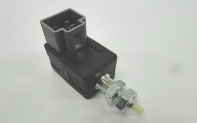
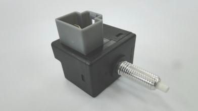
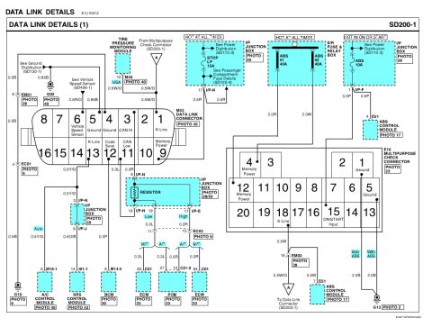
Connectors and switchesView all 4
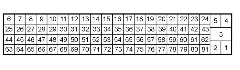
A numbered connector pinout diagram showing rows of small squares labeled with sequential numbers (6 through 81) plus a stacked group of larger cells numbered 1 through 5 on the right, representing an ECU connector layout.
Is this accurate? Sign in to help verify it.
No comments yet.