Home/
Registry/
Hyundai/
Accent/
2006-2011/
2008 Hyundai Accent/
Photo
supermotors.net/registry/media/1083285
Hyundai Accent Data Link Connector Wiring Diagram SD200-1 - OBD-II Pinout

Reference · 2006-2011 AccentAll 11 wiring diagrams
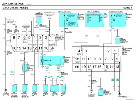
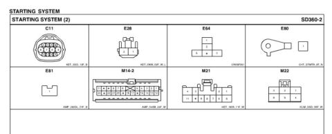
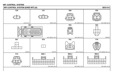
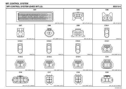
Wiring diagram titled DATA LINK DETAILS showing color-coded circuits, connector pin numbers and control-module connections.
Part of 2006-2011 Hyundai Accent Wiring Diagrams
This is page SD200-1, 'Data Link Details (1)', a factory-style wiring diagram covering the vehicle's data link (diagnostic) circuits. It shows the M33 Data Link Connector (16-pin OBD-II style) with pin assignments: pin 1 K-Line, pin 3 CAN Hi, pins 4/5 Ground, pin 6 Vehicle Speed Sensor, pin 9 Memory Power, pin 11 CAN Low, pin 12 Code Save, pin 13 K-Line. Power feeds include the STOP LP 15A fuse (hot at all times) in the I/P junction box for memory power, ABS #1 and ABS #2 40A fuses in the engine room fuse & relay box, and an ABS 10A fuse hot in ON or START. The diagram traces K-Line wiring (0.5Y/O and 0.5O/B) to the A/C control module and SRS control module, Code Save (0.3L) to the BCM, and CAN Hi/Low (0.3R/0.3L) through a resistor in the I/P junction box to the ECM (M/T) or PCM (A/T). It also details the E16 Multipurpose Check Connector (pins for Memory Power, Ground, K-Line, ON/START input), the Tire Pressure Monitoring Module connection (USA, pin 10 M46), the ABS control module (E51), and ground points G02, G13, G19, EM01, EM02. Wire gauges/colors (e.g., 2.0R, 2.0W, 0.5W/O) and cross-references to other diagram pages (SD110-3, SD120-4, SD130-1, SD436-1) are shown.
Is this accurate? Sign in to help verify it.
Frequently asked questions
- What are the pin assignments on the M33 data link connector?
- Top row: 8, 7, 6 (Vehicle Speed Sensor), 5 (Ground), 4 (Ground), 3 (CAN Hi), 2, 1 (K-Line). Bottom row: 16, 15, 14, 13 (K-Line), 12 (Code Save), 11 (CAN Low), 10, 9 (Memory Power).
- Which fuse supplies memory power to the data link connector?
- The STOP LP 15A fuse in the I/P junction box, which is hot at all times, feeds pin 17 I/P-N with a 0.5R wire to pin 9 (Memory Power) of the data link connector.
- Where do the CAN Hi and CAN Low wires from the diagnostic connector go?
- CAN Hi (0.3R) and CAN Low (0.3L) route through a resistor in the I/P junction box (I/P-N pins 9/18 and I/P-E pin 17), then via EC03 to the ECM (pins 62 and 84 of C01 on M/T) or the PCM (pins 27 and 12 of C01-2 on A/T).
- What fuses power the ABS in this diagram?
- ABS #1 40A and ABS #2 40A in the E/R fuse & relay box (hot at all times), plus an ABS 10A fuse in the I/P junction box that is hot in ON or START feeding the ABS control module (E51).
- What does the K-Line on connector pin 13 connect to?
- Pin 13 K-Line runs on a 0.5Y/O wire through the I/P junction box (I/P-N pin 3, I/P-J pin 9) to the A/C control module (pin 6 M16-1, Auto) and via 0.5O/B to the SRS control module (pin 14 I01-1).
No comments yet.