Oil Catch Can PCV Routing Diagram - Block to Can to Intake Manifold Setup

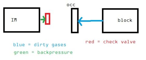
PCV hose routing diagram showing connections between the block, intake manifold, catch can, and check valve.
Part of 2004-2009 Mazda 3 Vacuum Routing Diagrams
This is a simple hand-drawn schematic diagram showing how to plumb an oil catch can into a vehicle's PCV (positive crankcase ventilation) system. The diagram depicts four elements: the engine block, the intake manifold (labeled "IM"), a catch can, and two valve locations marked with red rectangles. A hose is routed from the OEM PCV location on the engine block to the catch can, and a second hose runs from the catch can to the intake manifold. A check valve or PCV valve is shown inline on the hose between the catch can and the intake manifold, near the manifold connection. The document was uploaded to a 2008 Mazda 3 gallery as part of an album about oil catch cans and check valves. The diagram gives no year, make, model, part numbers, or dimensions, it is purely a conceptual routing illustration showing crankcase vapors flowing from the block, through the catch can (where oil vapor is separated), and then to the intake manifold, with a check valve preventing reverse flow. A reader can learn the correct hose routing order and valve placement for a basic catch can installation on the PCV side of the crankcase ventilation system.
Is this accurate? Sign in to help verify it.
Frequently asked questions
- How is the catch can plumbed in this setup?
- A hose runs from the OEM PCV location on the engine block to the catch can, and a second hose runs from the catch can to the intake manifold (IM).
- Where does the check valve go in this catch can setup?
- The check valve (or a PCV valve) is placed inline on the hose between the catch can and the intake manifold, near the IM connection.
- Where does the hose from the engine block connect?
- It connects from the OEM PCV location on the block to the catch can.
- Does this diagram specify part numbers or hose sizes?
- No. It is a conceptual routing diagram only, with no part numbers, hose sizes, or vehicle-specific details.
Comments
More from this build

No comments yet.