1970 Camaro F-Series A/C Hose Routing Diagram - GM Drawing 3965175 UPC C60

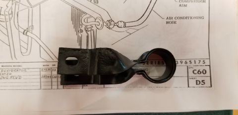
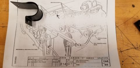
1970 Camaro A/C hose routing schematic with a metal mounting bracket laid on top of the printed drawing.
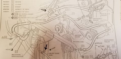
This is a scanned GM factory assembly/engineering drawing, number 3965175, titled "Air Conditioning - Hose Routing" for the 1970 Camaro "F" Series (Model 12000, UPC C60, Sheet D5). The drawing is an engine-bay illustration showing the routing of air conditioning hoses on the front of the vehicle. Callouts identify the heater hoses along the firewall, the compressor assembly (with its pulley) mounted on the engine, the air conditioning hose running from the compressor toward the front of the vehicle, and the receiver & dehydrator assembly mounted near the radiator support/core area. An arrow highlights a hose clamp/retainer point on a heater hose. The revision record shows two revisions: 9-26-69 ("REC & DEHYDRATOR RELOCATED", auth 27236) and 2-18-70 ("VALVE DWG REV'D", auth 28744), with a preliminary date of 9-2-69. A black metal strap/bracket (an actual part, apparently an exhaust or receiver-drier clamp) is lying on top of the paper, obscuring part of the upper-left area of the drawing. A reader can learn the correct factory routing and mounting locations of the A/C system hoses and major A/C components for a 1970 GM F-body with air conditioning (RPO C60).
Is this accurate? Sign in to help verify it.
Frequently asked questions
- What does GM drawing 3965175 show?
- It is the 1970 Camaro "F" Series "Air Conditioning - Hose Routing" drawing (UPC C60, Sheet D5, Model 12000), showing routing of the A/C and heater hoses and the locations of the compressor assembly and receiver & dehydrator assembly.
- Where is the receiver & dehydrator assembly located on a 1970 F-body with A/C?
- Per the drawing, the receiver & dehydrator assembly mounts at the front of the engine bay near the radiator/core support area, connected by A/C hoses; a 9-26-69 revision notes the receiver & dehydrator was relocated.
- What revisions were made to this drawing?
- Two revisions are recorded: 9-26-69, symbol 1, "REC & DEHYDRATOR RELOCATED" (auth 27236), and 2-18-70, symbol 2, "VALVE DWG REV'D" (auth 28744).
- What UPC/option code does this A/C drawing correspond to?
- The title block lists UPC C60 (air conditioning), Sheet D5, Model 12000.
- What components are labeled on the diagram?
- Heater hoses, compressor ASM, air conditioning hose, and receiver & dehydrator ASM.
Comments
More from this build



No comments yet.