1970 Pontiac Firebird A/C Hose Routing Diagram - Receiver-Dehydrator & POA Valve
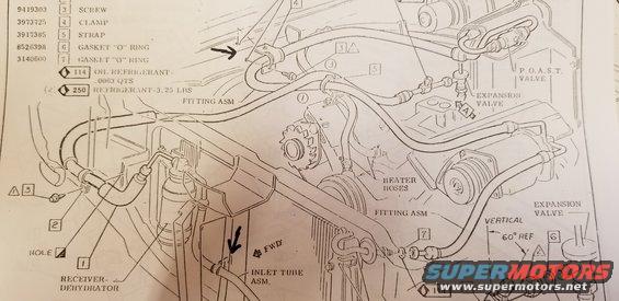
A/C system schematic showing hose routing, receiver-dehydrator, expansion valve and fitting assemblies with parts callouts.
This is a scanned page from a factory assembly manual / parts illustration showing the air conditioning refrigerant hose and line routing at the front of an engine compartment, uploaded to a 1970 Pontiac Firebird gallery. The exploded-view schematic depicts the A/C system components: the receiver-dehydrator mounted beside the radiator, the inlet tube assembly, fitting assemblies, hose routing over the engine, heater hoses, the expansion valve (shown installed at 60° from vertical per a reference detail), and the P.O.A.S.T. valve. A parts legend lists callout numbers with GM part numbers: 9419303 screw (3), 3973725 clamp (4), 3917385 strap (5), 8526398 O-ring gasket (6), and 3140600 O-ring gasket (7). Service fill specifications are given as refrigerant oil charge of .0063 quarts (spec code 114) and refrigerant charge of 3.25 lbs (spec code 250). Hand-drawn arrows mark two attachment/routing points of interest. A reader can learn correct A/C hose routing, clamp and strap locations, O-ring placement at fittings, the expansion valve mounting angle, and the system's refrigerant and oil capacities.
Is this accurate? Sign in to help verify it.
Frequently asked questions
- What is the refrigerant capacity shown on this diagram?
- The legend lists REFRIGERANT - 3.25 LBS (spec code 250).
- How much refrigerant oil does the diagram specify?
- OIL REFRIGERANT - .0063 QTS (spec code 114).
- What GM part numbers appear in the parts legend?
- 9419303 (screw), 3973725 (clamp), 3917385 (strap), 8526398 (gasket "O" ring), and 3140600 (gasket "O" ring).
- At what angle is the expansion valve mounted?
- A detail on the diagram shows the expansion valve oriented 60° from vertical (labeled '60° REF' next to 'VERTICAL').
- What major A/C components are labeled in the illustration?
- Receiver-dehydrator, inlet tube assembly, fitting assemblies, heater hoses, expansion valve, and the P.O.A.S.T. valve.
Comments
More from this build



No comments yet.