Home/
Registry/
Ford/
LTD Crown Victoria/
1980-1982/
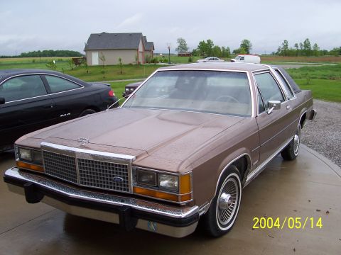
“Teh LTD”/
Photo
supermotors.net/registry/media/308044
Ford Speed Sensor AC Voltage Test Diagram: Meter Hookup (GH1953-B)

Reference · 1980-1982 LTD Crown VictoriaAll 4 service procedures
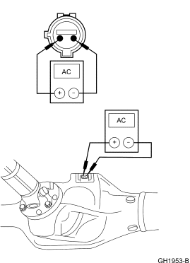
Service manual test figure showing an AC voltmeter connected to a sensor on a rear axle for a diagnostic measurement.
Part of 1980-1982 Ford LTD Crown Victoria Service Procedures
This document is a purely graphical service-procedure illustration identified by the figure number GH1953-B. It contains almost no text; the only legible labels are 'AC' and the polarity markings '(+)' and '(−)' on two meter faces. The upper illustration shows a close-up of a two-pin electrical connector (a round sensor connector with two terminals) with test leads from an AC voltmeter/multimeter probing its two pins. The lower illustration shows the same AC meter connected to a small two-terminal sensor mounted on top of what appears to be a transmission/transfer case or axle housing, indicating where the component is located on the vehicle and how to back-probe or connect the meter at the sensor. A reader can learn the correct hookup for testing a two-wire sensor (such as a speed sensor) by measuring its AC voltage output: connect the meter's positive and negative leads across the sensor's two pins, either at the disconnected connector or at the sensor on the housing. No fuse data, wire colors, torque values, part numbers (other than the figure code), specifications, or vehicle year/model applicability statements appear anywhere in the image.
Is this accurate? Sign in to help verify it.
Frequently asked questions
- What type of meter is shown in this diagram?
- An AC voltmeter/multimeter set to AC, with (+) and (−) leads connected to a two-pin sensor connector.
- How are the meter leads connected in this test?
- The (+) and (−) test leads are connected across the two pins of the sensor's connector, and in the second view directly at the sensor mounted on the housing.
- Where is the sensor being tested located?
- The lower illustration shows the two-terminal sensor mounted on top of a transmission/axle housing, with the AC meter leads attached to it.
- Does the diagram give any voltage specifications or values?
- No. The illustration only shows the AC meter hookup; no voltage readings, specs, or values are printed on it.
No comments yet.