Home/
Registry/
Ford/
Bronco/
1992-1996/
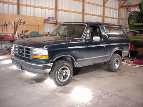
1994 Ford Bronco/
Photo
supermotors.net/registry/media/486208
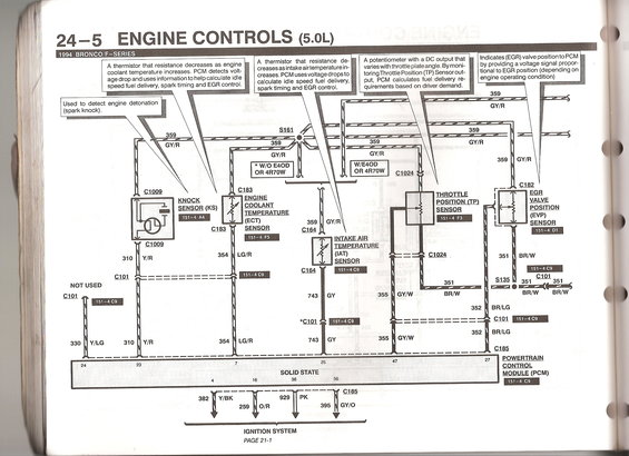
This diagram details the engine controls for a 1994 Ford Bronco 5.0L engine, illustrating various sensor inputs and outputs to the Powertrain Control Module.
24-5 ENGINE CONTROLS (5.0L) 1994 BRONCO/FSERIES A thermistor that resistance decreases as engine ll coolant temperature increases. PCM detects volt- age drop and uses information to help calculate idle speed iuel delivery, spark timing and EGFl control. Indicates (EGR) valve positionto PCM by providing a voltage signal propor tional to EGR position (depending on engine 0 eratin condition) A potentiometer with a DC output that = varieswiththrottle plateangle. By moni- toring Throttle Position (TP) Sensorout- put, PCM calculates fuel delivery re- quirements based on driver demand. A thermistor that resistance de- creasesasintakeairtemperaturein- - creases. PCM usesvoltage dropsto calculate idle speed fuel delivery, spark timing and EGR control. . ii i Used to detect engine detonation l (spark knock) .r 1"._ 359 VI--- GY/ R I I 359 : GY/R I 91.025 r_ 9.133 THR LE l :65 POSITI N TP VALVE SEASQB mu ' (EVP) I_ 531593 m _ m 351 BR/W 151-409 9191 351 $115 351 351 I1 I . NOT USED O GY 355 GY/W BR/W BR/W BR/W 9191 . 352 BR/LG I *901 ::::::::: c101 . l i I 51 5 TPSSIQSZT RE m: (Em) 352 BR/ LG POWERTRAIN QQNIRQL MQDuLE (PCM) _ 51 4 C9 SOLID STATE 4 16 36 . _' _ '_ _ 15 i 382 Y/ BK 929 PK 1 259 0/8 395 GY/O IGNITION SYSTEM PAGE 21-1
Comments
More from this build


No comments yet.