Home/
Registry/
Ford/
Bronco/
1992-1996/
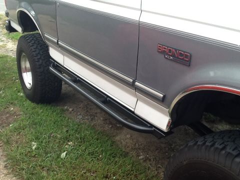
1994 Ford Bronco/
Photo
supermotors.net/registry/media/486207
1994 Ford Bronco/F-Series 5.0L Engine Controls Wiring Diagram - Injectors, IAC, EGR

Ford 1994 Bronco/F-Series 5.0L (without E4OD/4R70W) engine-controls schematic (24-4): fuel injectors, EGR control, AIRB/AIRD, canister purge and IAC solenoids wired to the PCM with circuit numbers.
Part of 1992-1996 Ford Bronco Wiring Diagrams
This is page 24-4 of a 1994 Ford Bronco/F-Series wiring diagram set, covering Engine Controls for the 5.0L engine without the E4OD or 4R70W transmission. The diagram shows the 12V relay-energized power feed (circuit 361, red wire) coming from splice S122 (page 24-1) through connector C101 to splice S149, which distributes power to the EGR control solenoid (C180), secondary air injection bypass (AIRB) solenoid (C1022), secondary air injection diverter (AIRD) solenoid (C1023), canister purge solenoid (C171), idle air control valve (C1007), and via splice S151 to all eight fuel injectors (C190 through C197). Ground/control-side circuits return to the Powertrain Control Module (PCM): circuit 360 BR/PK to pin 33 (EGR), 190 W/O to pin 51 (AIRB), 200 BR to pin 11 (AIRD), 101 GY/Y to pin 31 (canister purge), 264 W/LB to pin 21 (IAC), and injector driver circuits 556 W (pin 59) and 555 T (pin 58) via splices S159 and S160. Component location references (e.g., 151-4 A6, 151-4 F7, 151-4 C9) are given for each connector. Useful for diagnosing injector, IAC, EVAP purge, EGR, and air injection wiring on this drivetrain combination.
Is this accurate? Sign in to help verify it.
Frequently asked questions
- What PCM pin controls the idle air control (IAC) valve on the 1994 Bronco/F-Series 5.0L?
- The IAC valve (connector C1007) connects to PCM pin 21 via circuit 264, a white/light blue (W/LB) wire.
- What wire colors are used for the fuel injector control circuits?
- Injectors are grouped onto two circuits: 555 T (tan) going to PCM pin 58 and 556 W (white) going to PCM pin 59, joined at splices S159 and S160.
- Where do the fuel injectors get their 12V power?
- Power is circuit 361 (red wire), 12V when the relay is energized, fed from splice S122 (page 24-1) through connector C101 to splices S149 and S151, then to injector connectors C190 through C197.
- What circuit and PCM pin control the EGR control solenoid?
- The EGR control solenoid (connector C180, location 151-4 A6) uses circuit 360, a brown/pink (BR/PK) wire, to PCM pin 33.
- Does this diagram apply to trucks with the E4OD or 4R70W transmission?
- No: the page is titled 'Engine Controls (5.0L W/O E4OD or 4R70W)', so it applies only to 1994 Bronco/F-Series 5.0L vehicles without those transmissions.
Comments
More from this build









No comments yet.