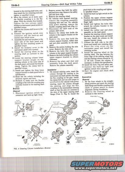
This diagram illustrates the step-by-step process for installing a steering column assembly, including various components and their connections.
] 3-06-3 located in the steering shaft slots, and then install the two retaining nuts and tighten to specied torque. 4. Move the column up or doWn until the exible coupling is in the at plane. With the column thus located, tighten the two column upper bracket-to-instrument panel screws to specied torque. 5 Connect the column shift levers to the shift rods. 6. Connect the ignition switch wire connector and the back-up and neutral start switch wires. 7. Assemble the seal and toe-plate to the inner side of the dash panel and tighten the four attaching screws to specied torque. 8. Install the modesty cover to the instrument panel (two screws). 9. Install the steering wheel on the steering shaft as outlined in this section. 10. Locate the steering column lower support bracket snugly on the steering column at the outer side of the dash panel, and install the bracket clampi Tighten the clamp bolt to specied torque. 11. Install and tighten the three lower support bracket-todash panel bolts to specication. 12. Road test the vehicle including the direction signals and horn. .Recheck to make sure the exible coupling is at with the coupling pins centrally located in the steering shaft slots. Bronco Removal 1. Disconnect ignition switch wire connector and back-up light wires. 1 w FLEX erEwc GEAR COUPUNG MANUAL / STEERING Steering ColumnShift Rod Within Tube 2. Remove screws that hold the safety pad and horn ring. Remove the safety pad and horn ring. 3. Remove the steering wheel. 4. On vehicles with manual steering, remove the coupling assembly retaining bolt and nut. On vehicles with power steering, remove the exible coupling pinch bolt (Fig. 4.) 5. Disconnect the shift rods at the column shift levers. 6. Remove the clamp that holds the column to the support bracket on the dash panel 7. Remove the nuts that hold the column support bracket, rubber dust seal and plate assembly on the dash panel. 8. Remove the screws holding the trim cover. Remove the trim cover. 9. Remove the bolts that attach the column to the upper support bracket, 10. Remove the bolts holding the column upper support bracket to obtain clearance. ll.Remove the plate and dust seal assembly from the dash panel. Remove the column assembly. Installation 1. On manual steering units, insert the column through the opening in the instrument and dash panels, and align the ex coupling on the gear. Install the clamp bolt and nut and torque to specificationOn vehicles with power steering, insert the column through the opening, and align the ex coupling on the intermediate steering shaft so that the pins are centered in the slots of the upper steering shaft ange (View U, Fig. 4). Install the SHlFT AND COLUMN ASSEMBLV TOE PLATE FIG. 4 Steering Column InstallationBronco INTERMEDIATE STEERlNG SHAFT POWER STEERlNG l 3-06-3 pinch bolt in the coupling and tighten to specied torque. 2. Install the back-up light switch on the column. 3. Position the upper column support brackets and install the retaining bolts nger tight. 4, Install and tighten the bolts that attach the column bracket to the support bracket. 5. Install the rubber seal and plate assembly on the dash panel. 6. Position the steering column support bracket on the plate studs and install the nuts. Install the column on the support bracket clamp. 7. Connect the shift rods to the shift levers and install new retaining clips. 8. Place the trim cover on the instrument panel and install the retaining screws. 9. Install the steering wheel on the steering shaft. The gap between the lower edge of the steering wheel hub and the steering column should be .03 to .06 inch. Loosen the column, if necessary, to obtain this specication. 10. Install the horn ring and safety pad. 11. Connect the back-up light and ignition switch wire connectori 12. Start the engine and check shift operation. Econoline Removal 1. Set the front wheels in the straight- ahead position and mark the steering shaft ange and exible coupling with chalk or grease pencil to retain alignment during installation. 2. Remove the steering wheel as outlined in this section. FLEX COUPLlNG ASSEMBLY CLAMP LOWER BRACKET SHAFT AND JOlNT i GISGSvC
Comments
More from this build

No comments yet.