Home/
Registry/
Mercury/
Cougar/
1989-1997/
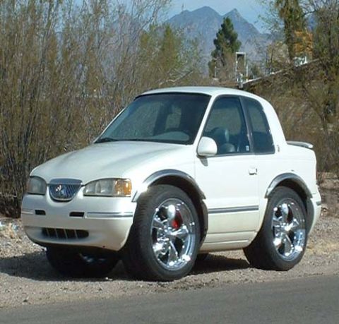
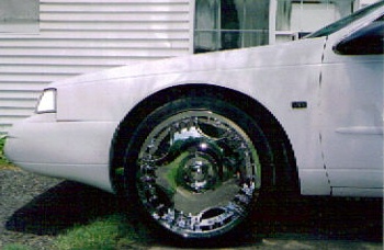
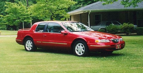
1997 Mercury Cougar/
Photo
supermotors.net/registry/media/728729
4.6L Vacuum Distribution Diagram - EVR, IAC, EVAP Purge & Brake Booster Routing
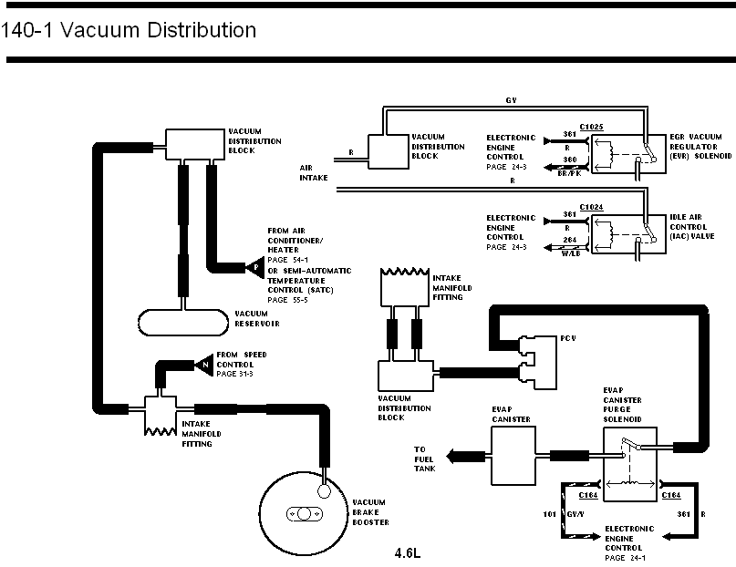
Ford 4.6L vacuum distribution routing (page 140-1): intake manifold and distribution blocks feeding vacuum reservoir, brake booster, SATC, EGR vacuum regulator C1025, IAC valve C1024 and EVAP canister purge solenoid.
Part of 1989-1997 Mercury Cougar Vacuum Routing Diagrams
This document is page 140-1, titled "Vacuum Distribution," showing the vacuum routing diagram for a 4.6L engine. It depicts vacuum distribution blocks connected to the air intake and intake manifold fittings, with routing to the vacuum reservoir, PCV valve, EVAP canister, EVAP canister purge solenoid, vacuum brake booster, and fuel tank. It also shows vacuum feeds coming from the air conditioner/heater or semi-automatic temperature control (SATC) system (referenced on pages 54-1 and 55-5) and from the speed control system (page 31-3). Electrical connections are included for three solenoids/valves: the EGR Vacuum Regulator (EVR) solenoid at connector C1025 with circuits 361 R and 360 BR/PK; the Idle Air Control (IAC) valve at connector C1024 with circuits 361 R and 264 W/LB; and the EVAP canister purge solenoid at connector C164 with circuits 101 GY/Y and 361 R. All three electrical circuits reference the Electronic Engine Control diagrams (pages 24-1 and 24-3). A reader can learn the complete vacuum hose routing layout and the wire colors, circuit numbers, and connectors for the vacuum-related engine control solenoids on the 4.6L engine.
Is this accurate? Sign in to help verify it.
Frequently asked questions
- What engine does this vacuum distribution diagram cover?
- The diagram is labeled 4.6L, so it covers the 4.6L engine's vacuum distribution.
- What connector and wires go to the EGR Vacuum Regulator (EVR) solenoid?
- Connector C1025, with circuit 361 R (red) and circuit 360 BR/PK (brown/pink), connecting to the Electronic Engine Control (page 24-3).
- What are the wiring details for the Idle Air Control (IAC) valve?
- The IAC valve uses connector C1024 with circuits 361 R and 264 W/LB, connected to the Electronic Engine Control (page 24-3).
- How is the EVAP canister purge solenoid wired?
- It connects through connector C164 with circuits 101 GY/Y and 361 R, going to the Electronic Engine Control (page 24-1). Vacuum-wise it connects between the EVAP canister and the vacuum distribution block, with the canister also routing to the fuel tank.
- Where does the vacuum brake booster get its vacuum?
- The vacuum brake booster is fed from an intake manifold fitting through the vacuum hose routing shown in the diagram.
Comments
More from this build
No comments yet.