Home/
Registry/
Mercury/
Cougar/
1989-1997/
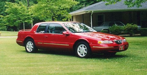
1997 Mercury Cougar/
Photo
supermotors.net/registry/media/859418
2000 Mercury Cougar Cooling Fan Wiring Diagram - Low/High Relays & PCM Control

Wiring diagram of the engine cooling fan circuit showing fan relays, PCM, fuses, and color-coded wiring to the cooling fan motor.
Part of 1989-1997 Mercury Cougar Wiring Diagrams
This document is a Ford/Mercury cooling fan wiring diagram (filed as "2000_coolingfan") showing the electric engine cooling fan circuit. Power comes from two Battery Junction Box sources that are hot at all times: fuse/circuit breaker position 17 (30A c.b., page 13-6) feeding circuit 1155 YE/BK, and position 13 (50A, page 13-1) feeding circuit 1153 RD/BK. In Start or Run, the PCM Power Relay (Relay Center, pages 23-1, 24-1) supplies circuit 361 RD through splice S116 to both the Cooling Fan Low Relay and the Cooling Fan High Relay (High Current Relay Center). The Powertrain Control Module (pins 28 and 46, connector C185) grounds circuit 229 RD/OG or 639 LG/VT to energize the low or high fan relay; a callout explains that when the PCM determines fan operation is required, it grounds either relay to turn on the Cooling Fan Motor. Relay outputs 228 DB and 638 OG/LB feed the Cooling Fan motor via connector C109, with ground through circuit 57 BK to ground point G102 (see Grounds, pages 10-2, 10-3). Connectors C103F/C103M are shown in the 639 LG/VT circuit. Cross-references to Engine Controls pages 23-2, 23-8, 24-1, 24-2 and 24-6 are included.
Is this accurate? Sign in to help verify it.
Frequently asked questions
- How does the PCM control the cooling fan in this diagram?
- A callout states that when the PCM determines fan operation is required, it grounds either the cooling fan low relay (circuit 229 RD/OG, PCM pin 46) or the cooling fan high relay (circuit 639 LG/VT, PCM pin 28) to turn on the Cooling Fan Motor.
- What fuses/circuit protection feed the cooling fan circuit?
- Two Battery Junction Box sources hot at all times: position 17, a 30A circuit breaker (page 13-6) on circuit 1155 YE/BK, and position 13, a 50A fuse (page 13-1) on circuit 1153 RD/BK.
- What wire colors are used for the cooling fan relays and motor?
- 361 RD (relay coil power from the PCM power relay via splice S116), 1155 YE/BK and 1153 RD/BK (battery feeds), 228 DB (low relay output), 638 OG/LB (high relay output to fan), 229 RD/OG and 639 LG/VT (PCM control grounds), and 57 BK (fan ground to G102).
- Which connectors are in the cooling fan circuit?
- C103F/C103M in the 639 LG/VT circuit, C185 at the PCM, and C109 at the cooling fan motor; ground is at G102 (see Grounds, pages 10-2, 10-3).
- Where is the Cooling Fan High Relay located?
- The diagram places the Cooling Fan High Relay in the High Current Relay Center; the Cooling Fan Low Relay and PCM Power Relay are also shown (PCM Power Relay in the Relay Center).
Comments
More from this build





No comments yet.