Jaguar XJ6 Fueling Control / Metering Component Location Diagram
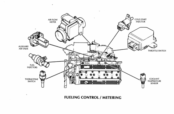
Fuel injection control/metering schematic identifying the air flow meter, auxiliary air valve, fuel injectors, cold start injector, throttle switch and temperature sensors.
Part of 1979-1987 Jaguar XJ6 Schematics
This document is a labeled component-location diagram titled "FUELING CONTROL / METERING." It shows a side view of an inline six-cylinder engine with callout illustrations of seven fuel-system components, each drawn individually and connected by leader lines to its mounting location on the engine. The identified components are: the air flow meter (shown at the top with the throttle body/intake), the cold start injector (upper right, pointing to the intake manifold area), the auxiliary air valve (left side), the fuel injectors (left, pointing to the fuel rail along the intake side), the thermotime switch (lower left, pointing to a location on the block/manifold), the throttle switch (right side, a rectangular module with multi-pin connectors), and the coolant temperature sensor (lower right, pointing to the cylinder head area). A reader can use this diagram to identify what each fueling/metering component looks like and where it is physically located on the engine, which is useful for diagnosing fuel injection problems or locating sensors for testing and replacement. The document contains no part numbers, wire colors, specifications, or year/model text, it is purely a pictorial identification and location guide for the electronic fuel injection metering components.
Is this accurate? Sign in to help verify it.
Frequently asked questions
- What components are shown in this fueling control/metering diagram?
- The diagram identifies the air flow meter, cold start injector, auxiliary air valve, fuel injectors, thermotime switch, throttle switch, and coolant temperature sensor, each with a leader line to its location on the engine.
- Where is the cold start injector located?
- The diagram shows the cold start injector at the upper right, with its leader line pointing to the intake manifold area near the center of the engine.
- Where is the coolant temperature sensor on this engine?
- The coolant temperature sensor is shown at the lower right of the diagram, with a leader line pointing to the cylinder head/intake side of the engine.
- Does this diagram show the throttle switch?
- Yes. The throttle switch is illustrated at the right side as a rectangular module with multi-pin connectors, with a leader line to its mounting location on the engine's intake side.
Comments
More from this build

No comments yet.