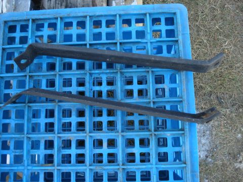
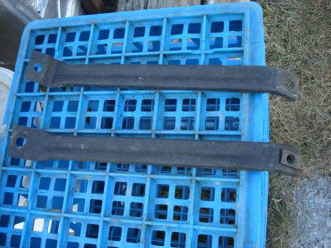
This document provides installation instructions for Lakewood Traction Bars, fitting various Ford and Chevy trucks.
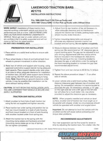
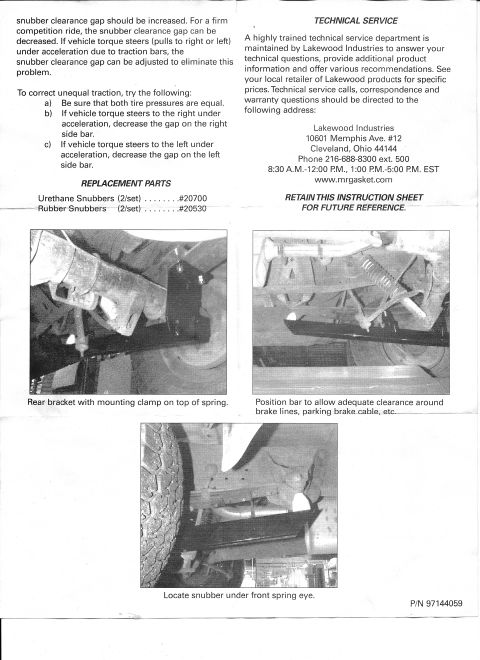
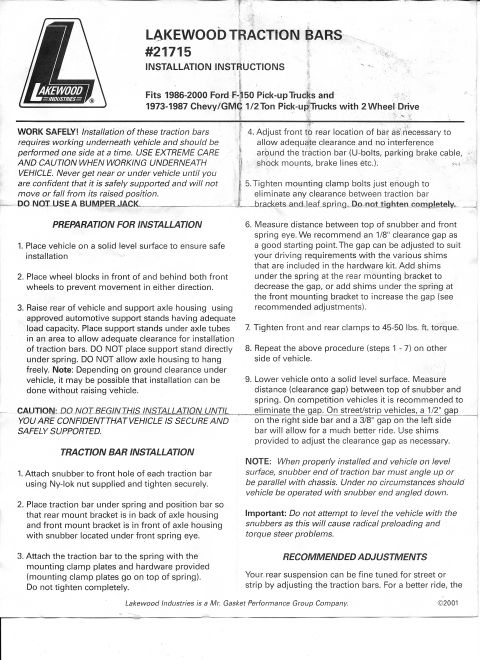
#21715 Akin/000 =llVDl/STRIES: l LAKEWOOD TRACTION IARS INSTALLATION INSTRUCTIONS l L I Fits 1986- 2000 Ford F-150 Pick- upTrucks and 1973- 1987 Chevy/GMC 1/2Ton Pick- upTrucks with 2WheeI Drive WORK SAFELY! Installation of these traction bars requires working underneath vehicle and should be performed one side at a time. USE EXTREME CARE AND CAUTION WHEN WORKING UNDERNEATH VEHICLE. Never get near or under vehicle until you are condent that it is safely supported and will not move or fall from its raised position. _.D.O NOIUSEABUMBEILIACKLNW. PREPARATION FOR INSTALLATION 1. Place vehicle on a solid level surface to ensure safe installation 2. Place wheel blocks in front of and behind both front wheels to prevent movement in either direction. 3. Raise rear of vehicle and support axle housing using approved automotive support stands having adequate load capacity. Place support stands under axle tubes in an area to allow adequate clearance for installation of traction bars. DO NOT place support stand directly under spring. DO NOT allow axle housing to hang freely. Note: Depending on ground clearance under vehicle, it may be possible that installation can be done without raising vehicle. CAUTION; DO NOIBEGINTHIS INSTALLAZIQNLLNIILA YOU ARE CONFIDENTTHAT VEHICLE IS SECURE AND SAFELY SUPPORTED. TRACTION BAR INSTALLATION 1. Attach snubber to front hole of each traction bar using Nylok nut supplied and tighten securely. 2. Place traction bar under spring and position bar so that rear mount bracket is in back of axle housing and front mount bracket is in front of axle housing with snubber located under front spring eye. 3. Attach the traction bar to the spring with the mounting clamp plates and hardware provided (mounting clamp plates go on top of spring). Do not tighten completely. Lakewood Industries is a Mr. Gasket Performance Group Company. 4. Adjust front to rear location of bar asnecessary to allow adequate clearance and no interference around the traction bar (U bolts, parking brake cable, If: shock mounts, brake lines etc). -~ VI 5 Tighten mounting clamp bolts just enough to eliminate any clearance between traction bar ,,.~.,'M_bra.ckets endleatspringtDornottighten completely. , 6. Measure distance between top of snubber and front spring eye. We recommend an 1/8" clearance gap as a good starting point.The gap can be adjusted to suit your driving requirements with the various shims that are included in the hardware kit. Add shims under the spring at the rear mounting bracket to decrease the gap, or add shims under the spring at the front mounting bracket to increase the gap (see recommended adjustments). 7. Tighten front and rear clamps to 4550 lbs. ft. torque. 8. Repeat the above procedure (steps 1 7) on other side of vehicle. 9. Lower vehicle onto a solid level surface. Measure distance (clearance gap) between top of snubber and spring. On competition vehicles it is recommended to eliminate the gap. On street/strip vehicles, a 1/2" gap on the right Side bar and a 3/8" gap on the left side bar will allow for a much better ride. Use shims provided to adjust the clearance gap as necessary. NOTE: When properly installed and vehicle on level surface, snubber end of traction bar must angle up or be parallel with chassis. Under no circumstances should vehicle be operated with snubber and angled down. Important: Do not attempt to level the vehicle with the snubbers as this will cause radical preloading and torque steer problems. RECOMMENDED ADJUSTMENTS Your. rear suspension can be fine tuned for street or strip by adjusting the traction bars. For a better ride, the @2001
Comments
More from this build
No comments yet.