Home/
Registry/
Dodge/
Ramcharger/
1981-1993/
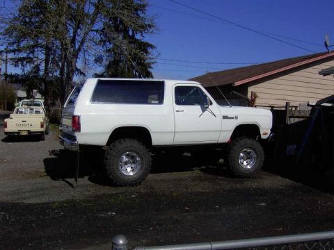
1987 Dodge Ramcharger/
Photo
supermotors.net/registry/media/885302
Dodge 5.9L (360) Vacuum Hose Routing Diagram 4405730 - Chrysler Underhood Decal
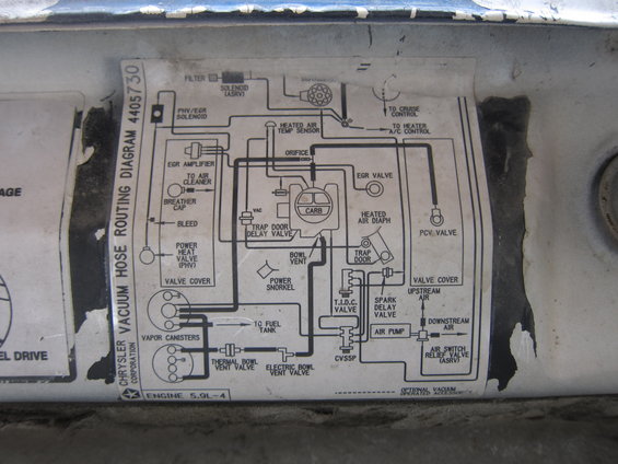
Chrysler 5.9L V8 vacuum hose routing diagram showing labeled connections for carburetor, valves and air pump.
Part of 1981-1993 Dodge Ramcharger Vacuum Routing Diagrams
This is a photograph of a factory Chrysler Corporation underhood decal, "Vacuum Hose Routing Diagram 4405730," for the 5.9L engine (labeled "ENGINE 5.9L-4"). The schematic shows the complete emissions and vacuum hose routing for a carbureted 5.9L V8. Components illustrated and labeled include the carburetor (CARB), EGR valve, EGR amplifier, PHV/EGR solenoid, air switch relief valve (ASRV) solenoid with filter, distributor, heated air temperature sensor, heated air diaphragm, trap door and trap door delay valve, orifice, PCV valve, breather cap, bleed, power heat valve (PHV), power snorkel, bowl vent, dual vapor canisters (with line to fuel tank), thermal bowl vent valve, electric bowl vent valve, T.I.D.C. valve, spark delay valve, CVS5P, air pump with upstream/downstream air routing, and air switch relief valve (ASRV). Vacuum take-offs to cruise control and heater/A/C control are shown, and a dashed-line legend indicates optional vacuum-operated accessories. A reader can use this decal to verify or restore correct vacuum hose connections on the 5.9L (360) carbureted Dodge engine, particularly for emissions system components. The decal carries Chrysler part number 4405730 but shows no model year or vehicle model.
Is this accurate? Sign in to help verify it.
Frequently asked questions
- What engine does this vacuum diagram cover?
- The decal is labeled "ENGINE 5.9L-4," a carbureted Chrysler 5.9L engine (the diagram shows a carburetor, air pump, and EGR system).
- What is the part number of this Chrysler vacuum routing decal?
- It is Chrysler Corporation Vacuum Hose Routing Diagram 4405730.
- What emissions components are shown in the routing?
- EGR valve, EGR amplifier, PHV/EGR solenoid, ASRV solenoid and air switch relief valve, air pump (upstream/downstream air), PCV valve, dual vapor canisters, thermal and electric bowl vent valves, T.I.D.C. valve, spark delay valve, trap door delay valve, and CVS5P.
- Where do the accessory vacuum lines go?
- The diagram shows vacuum lines routed to cruise control and to the heater A/C control, with dashed lines indicating optional vacuum-operated accessories.
- Does the diagram show the vapor canister routing?
- Yes: two vapor canisters are shown connected to the fuel tank line, thermal bowl vent valve, electric bowl vent valve, and carburetor bowl vent.
Comments
More from this build
No comments yet.