Home/
Registry/
Chevrolet/
C/K Pickup/
1988-1998/
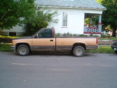
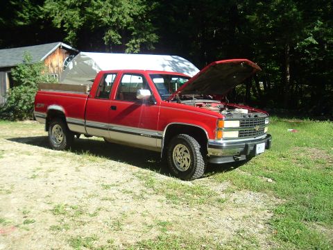
“BigGoldDuallie SOLD”/
Photo
supermotors.net/registry/media/894197
2001 6.5L Diesel Glow Plug Relay Wiring Diagram OBD-II - GM Chevy/GMC Schematic
Reference · 1988-1998 C/K PickupAll 2 wiring diagrams
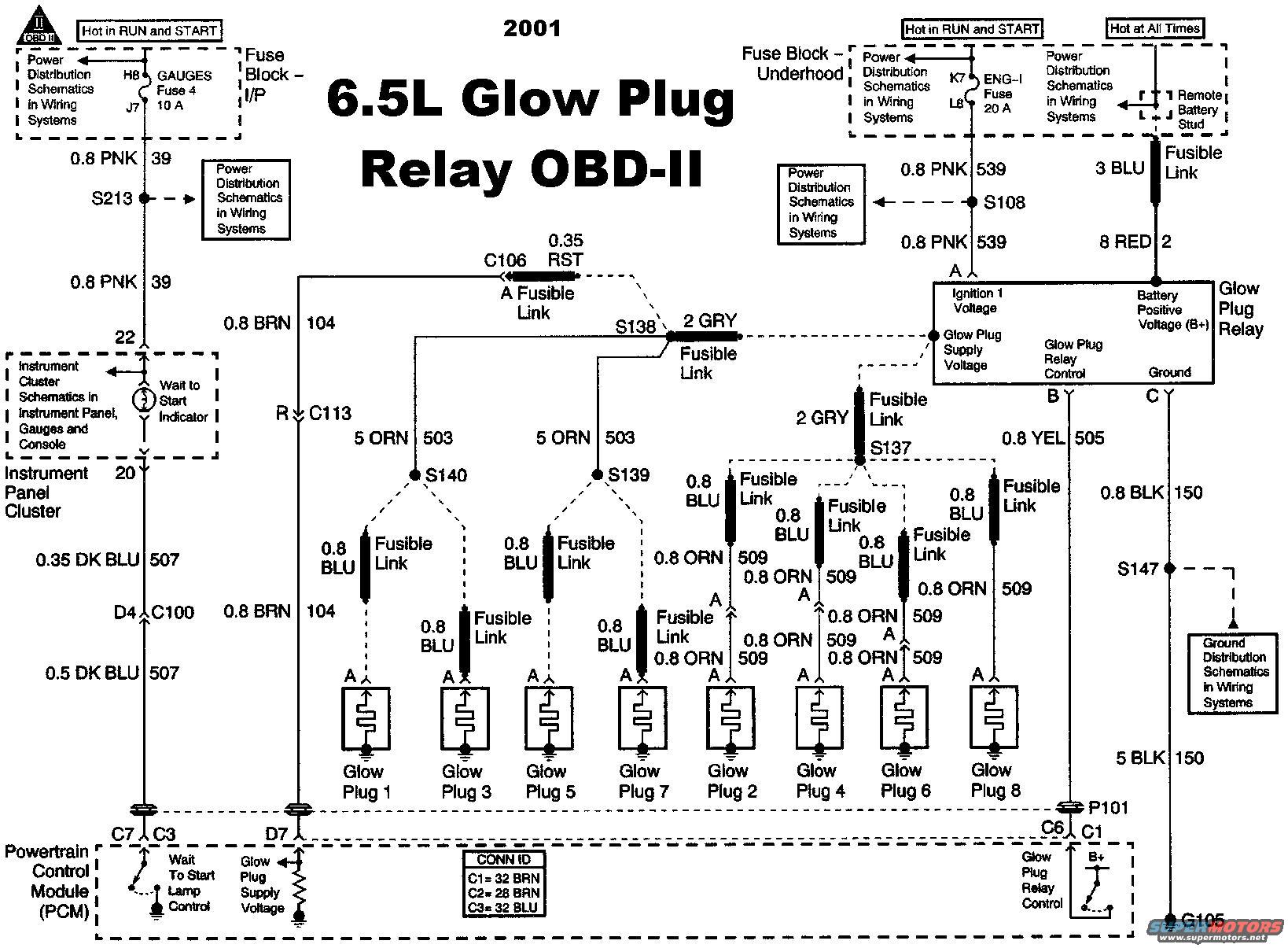
2001 6.5L diesel Glow Plug Relay (OBD-II) wiring diagram: PCM-controlled relay, fusible links and circuit 509 feeding all 8 glow plugs; gauges fuse 10A, fuse-block sources shown.
Part of 1988-1998 Chevrolet C/K Pickup Wiring Diagrams
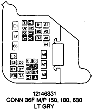
This document is a 2001 wiring schematic for the 6.5L diesel glow plug relay system (OBD-II). It shows power feeds from the I/P fuse block (GAUGES Fuse 4, 10 A, hot in RUN and START, cavities H8/J7), the underhood fuse block (ENG-I Fuse, 20 A, hot in RUN and START, cavities K7/L8), and a hot-at-all-times feed from the remote battery stud through a 3 BLU fusible link and 8 RED wire (circuit 2) to the glow plug relay's battery positive terminal. The glow plug relay has terminals for Ignition 1 Voltage, Battery Positive Voltage (B+), Glow Plug Supply Voltage, Glow Plug Relay Control (terminal B, 0.8 YEL circuit 505), and Ground (terminal C, 0.8 BLK/5 BLK circuit 150 to G105 via S147). Glow plug supply feeds through 2 GRY fusible links and splices S138, S140, S139, and S137 to eight individual glow plugs, each protected by its own 0.8 BLU fusible link (0.8 ORN circuit 509 on plugs 2, 4, 6, 8). The PCM controls the Wait To Start lamp (0.35/0.5 DK BLU circuit 507) and the glow plug relay, with connectors identified as C1=32 BRN, C2=28 BRN, C3=32 BLU. Wire colors, gauges (metric mm²), circuit numbers, splice, ground, and connector IDs are labeled throughout.
Is this accurate? Sign in to help verify it.
Frequently asked questions
- What fuses power the 6.5L glow plug relay circuit in this diagram?
- GAUGES Fuse 4 (10 A) in the I/P fuse block and the ENG-I Fuse (20 A) in the underhood fuse block, both hot in RUN and START. Battery positive comes from the remote battery stud (hot at all times) through a 3 BLU fusible link.
- What circuit and wire feed the glow plug relay's battery positive terminal?
- An 8 RED wire, circuit 2, coming from the remote battery stud through a 3 BLU fusible link.
- How are the individual glow plugs protected in this circuit?
- Each of the eight glow plugs has its own 0.8 BLU fusible link, fed from splices S140, S139, and S137 via 5 ORN circuit 503 and 0.8 ORN circuit 509 wires.
- What wire controls the glow plug relay from the PCM?
- The Glow Plug Relay Control signal on terminal B uses a 0.8 YEL wire, circuit 505, going to the PCM through connector P101 (C6/C1).
- Where does the glow plug relay ground?
- Terminal C grounds through a 0.8 BLK circuit 150 wire to splice S147, then a 5 BLK circuit 150 wire to ground G105.



No comments yet.