
Diagram illustrating the E4OD transmission control system for a 1995 Ford Bronco, detailing electrical connections and component functions.
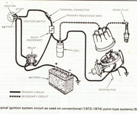
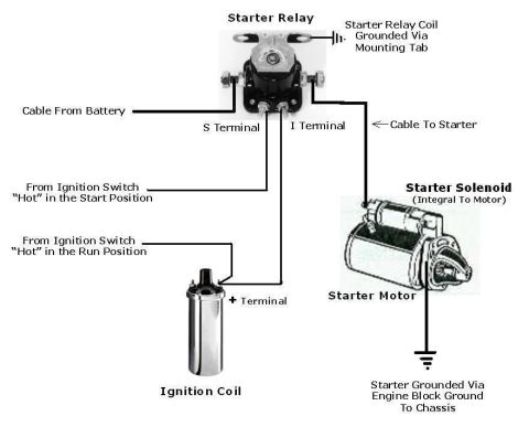
30-1 E4OD TRANSMISSION 1995 BRONCO For diagnostic information, refer to Power- train Control/Emissions Diagnosis Manual. POWERTRAlN CONTROL MODULE (PCM) PAGES 24-6, 25-4, 2510 HOT AT ALL TIMES HOT IN START OR RUN H The BOO switch F SE sends asignal'to | PANEL SEE ENGINE 359 GY/R the PCM to dis- 'PAGES 13-7, CONTROLS N engage the -- 1311 PAGE824-6,25-4, 0 orque conve er 25-11 CIUtCh when the SEE POWER C103M brake peda'T IS 236 o 383 540 I R DISTRIBUTION W cm depressed. hIs - R/W PAGES 13-7, 13-11 359 SIgnal may be Ig I we 0 mm ggladif TIgysi :1; 1o LG/R TURN /STop/ . 5321 Indicates that 4th gear has / mm! is above cloied HAZARD LAMPS been dIsengaged. May also PAGE 904 640 RH flash if monitored sensor/ac- I 12v 0279 TRANS MISSION BRAKE RANGE (TR) ' ON OFF (BOO) 3 Mia am I CLOSED WITH BRAKE PAGE 93" ZSZQVITCH Hm PEDAL DEPRESSED TRANSM'SS'N SEE PAGE CLOSED) com 149-?CFOR SEE TURN/STOP/ 5 I LG SWITCH TEQTINHG :ggg2LAMPS _51-6 F2 N l. A momentary contact switch 12V (SWITCH 0N) 0275M & that SIgn_a|s W? P GM to allow c275I= This sensorIncorporateS aseries ofstep down resistors automatIc Sh's from ISt which act as a voltage divider. The PCM monitors the 199 LB/Y through 4th or from 13t 9" W/LG voltage which correspondsto thebosition Ofthe manu- through 3rd gears. 4 T /W al lever. This information is used in determining desired (:1an _ C202F gear and EPC pressure. This sensor also houses the c103,| " c202M START circuits for the ignition system to allow the ve 511 T hicle to be started in PARK or NEUTRAL. The Backup 12V 224 TM 911 W/LG Lamp and 4X4 low-neutral sense circuits, which are 199 LB/y lL-(gLMtsng) Igwncn CLOSED closed in reverse are also contained within this sensor. CT 85 POWERTRAIN CONTROL MODULE (PCM) PAGES 243, 24-6, 25-2, 25-3 511 C10 - . Uses information from various sensors/actuators to de " /t
Comments
More from this build


No comments yet.