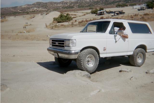
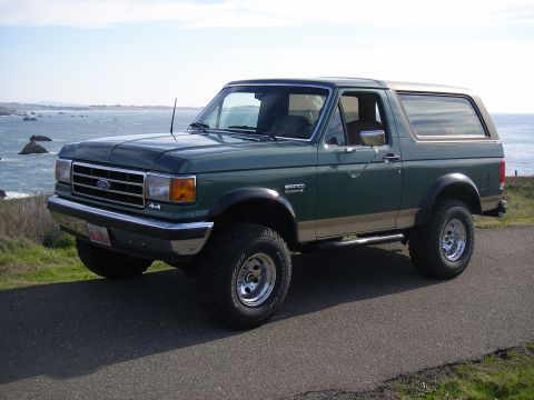
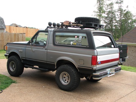
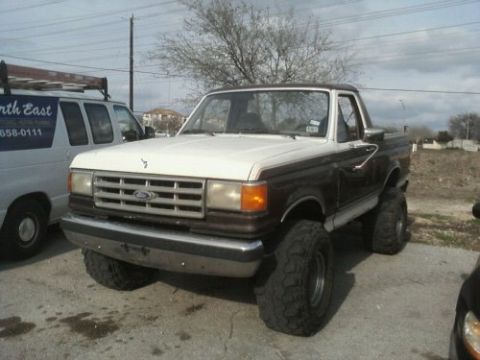
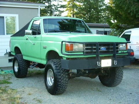
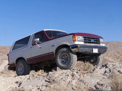
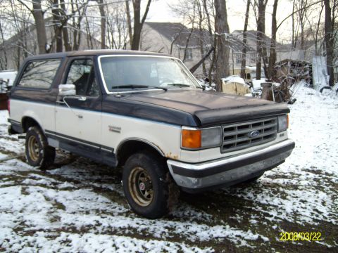
The fourth-generation Ford Bronco ran from 1987 through 1991 on the redesigned F-series "Bricknose" body, named for the flush, aerodynamic front clip with flush headlamps that replaced the boxy Bullnose face. For 1987 Ford gave the 4.9L (300) inline-six electronic fuel injection and added rear-wheel anti-lock brakes (RABS) as standard equipment, two of the generation's defining mechanical changes; the 5.0L (302) V8 carried over its existing multi-port electronic fuel injection from the third generation. The optional 5.8L (351 Windsor) V8 stayed carbureted for 1987 and received EFI for the 1988 model year. The engine roster carried the 4.9L (300 cubic inch) inline-six as the base unit, with the 5.0L (302) and 5.8L (351 Windsor) V8s optional. The Bronco kept its full-size two-door wagon body with a removable fiberglass rear hardtop over a 104.7-inch wheelbase, sharing its structure with the F-150 ahead of the B-pillar. Twin-Traction Beam (TTB) independent front suspension carried over from the third generation, as did the basic engine family, so the 1987 changes were fuel injection, braking, and styling rather than a new chassis. The Mazda-built M5OD five-speed overdrive manual replaced the older four-speed manual around 1988, and the biggest later mechanical addition was the E4OD four-speed overdrive automatic for 1990. The base trim was called Custom for 1987 and was renamed XL for 1988; above it sat the better-equipped XLT and the upscale Eddie Bauer.
Other Ford Bronco generations
At a glance
- Years: 1987-1991 (fourth generation, "Bricknose")
- Body style: two-door full-size wagon with removable fiberglass rear hardtop, 104.7-inch wheelbase
- Engines: 4.9L (300) inline-six, 5.0L (302) V8, 5.8L (351 Windsor) V8
- Fuel system: electronic fuel injection on the 4.9L six from 1987; the 5.0L V8 carried over its existing fuel injection; the 5.8L V8 was carbureted in 1987 and gained EFI for 1988
- Transmissions: 4-speed and 5-speed manuals, 3-speed and 4-speed automatics; the Mazda-built M5OD 5-speed overdrive manual replaced the 4-speed manual around 1988, and the E4OD 4-speed automatic arrived for 1990
- Front suspension: Twin-Traction Beam (TTB) independent front axle, carried over from the third generation
- Brakes: front disc, rear drum, with rear-wheel anti-lock brakes (RABS) standard from 1987
- Axles: Dana 44 TTB front axle; Ford 8.8-inch semi-floating rear axle
- Trims: base trim (Custom for 1987, renamed XL for 1988), XLT, Eddie Bauer
Year-by-year changes
| Year | Engines | Drivetrain & brakes | Notable changes |
|---|---|---|---|
| 1987 | 4.9L (300) six gains fuel injection; 5.0L (302) V8 fuel-injected (carried over); 5.8L (351W) V8 carbureted | Manual and automatic options; Dana 44 TTB front axle; Ford 8.8-inch semi-floating rear; front disc/rear drum with standard rear-wheel ABS (RABS) | Bricknose redesign: flush aerodynamic front end, electronic fuel injection on the 4.9L six, and standard rear-wheel anti-lock brakes |
| 1988 | 4.9L (300) six, 5.0L (302) V8, 5.8L (351W) V8, all fuel-injected | Dana 44 TTB front axle; Ford 8.8-inch semi-floating rear; front disc/rear drum with rear-wheel ABS | 5.8L V8 gained multi-port EFI, completing the fuel-injected lineup; the Mazda-built M5OD 5-speed overdrive manual replaced the 4-speed manual around this year; the base trim was renamed from Custom to XL |
| 1989 | 4.9L (300) six, 5.0L (302) V8, 5.8L (351W) V8, fuel-injected | Dana 44 TTB front axle; Ford 8.8-inch semi-floating rear; front disc/rear drum with rear-wheel ABS | Mostly carryover; continued running changes to interior and equipment |
| 1990 | 4.9L (300) six, 5.0L (302) V8, 5.8L (351W) V8, fuel-injected | E4OD 4-speed electronic automatic introduced; Dana 44 TTB front axle; Ford 8.8-inch semi-floating rear; front disc/rear drum with rear-wheel ABS | Arrival of the E4OD overdrive automatic transmission |
| 1991 | 4.9L (300) six, 5.0L (302) V8, 5.8L (351W) V8, fuel-injected | E4OD available; Dana 44 TTB front axle; Ford 8.8-inch semi-floating rear; front disc/rear drum with rear-wheel ABS | Final year of the Bricknose Bronco before the 1992 OBS fifth-generation redesign; the blacked-out "Nite" appearance package was offered |
Engines and drivetrain
The fourth-generation Bronco (1987-1991) used three gasoline engines. For 1987 the 4.9L six gained electronic fuel injection and the 5.0L V8 carried over its existing multi-port electronic fuel injection, while the 5.8L V8 was still carbureted and did not get EFI until the 1988 model year. The base 4.9L inline-six (300 cubic inches) was a long-running, low-revving truck engine valued for torque and durability. The optional 5.0L (302) and 5.8L (351 Windsor) small-block V8s gave more power for towing and the Bronco's roughly 4,500-pound curb weight. Manual and automatic transmissions were offered through the run. Around 1988 the Mazda-built M5OD five-speed overdrive manual replaced the older four-speed manual, and the significant automatic change came for 1990, when Ford introduced the E4OD, a four-speed electronically controlled automatic with overdrive that replaced the older three-speed automatic in many configurations. All 1987-1991 Broncos were built as four-wheel-drive trucks, with standard part-time four-wheel drive and a two-speed transfer case.
Axles and suspension
The 1987-1991 Bronco carried over the Twin-Traction Beam (TTB) independent front suspension that the third-generation Bronco had introduced for 1980. TTB uses two long swing arms (beams) pivoting near the frame's centerline, giving each front wheel independent travel while retaining a live-axle-style design with coil springs up front. Four-wheel-drive Broncos paired TTB with a Dana 44 front axle, while the rear axle was a Ford 8.8-inch semi-floating unit. The Ford 8.8-inch rear axle replaced the 9-inch rear axle used by the previous generation. The TTB layout improved ride quality over a solid front axle but is known among owners for camber change during suspension travel and for alignment quirks, traits that carried straight into this generation from the Bullnose era.
What changed for 1987 versus what carried over
Two features were genuinely new to the Bronco for 1987: electronic fuel injection on the 4.9L six, and standard rear-wheel anti-lock brakes (RABS), a rear-axle ABS system that helped prevent rear-wheel lockup under hard braking on a vehicle prone to light rear loading. The 5.0L V8 carried over its existing multi-port electronic fuel injection from the third generation rather than gaining it for 1987. The 5.8L V8 stayed carbureted for 1987 and joined the fuel-injected lineup for the 1988 model year. The Bricknose front-end styling, with its flush composite headlamps and smoother aerodynamic nose, was also new for 1987 and shared with the F-series trucks. By contrast, the TTB front suspension, the two-door wagon body, the 104.7-inch wheelbase, and the basic 4.9L/5.0L/5.8L engine family were carried over from the 1980-1986 third generation. Buyers researching this generation should not credit 1987 with the TTB suspension itself, which debuted in 1980.
Body and trims
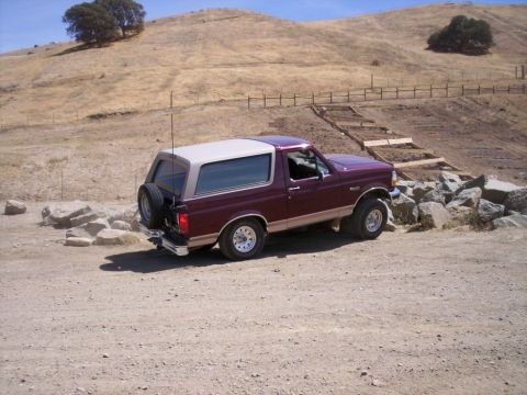
Every 1987-1991 Bronco was a full-size two-door wagon with a removable fiberglass top over the rear cargo and seating area, a body shared structurally with the F-150 ahead of the B-pillar. Trim levels ran from the base trim, called Custom for 1987 and renamed XL for 1988, through the better-equipped XLT to the top Eddie Bauer, the latter typically distinguished by two-tone paint, special wheels, and upgraded interior trim. For 1991 a blacked-out "Nite" appearance package was also offered. The Bricknose interior was updated alongside the F-series, with revised dashboards and switchgear over the run. The rear hardtop remained removable for open-air use, a defining trait the Bronco kept until the 1996 end of the full-size line.
What to know when buying a 1987-1991 Bronco
On a fourth-generation Bronco, the early multi-port fuel injection is generally reliable but depends on aging sensors, wiring, and the throttle body staying clean; driveability faults on these trucks often trace to vacuum leaks and worn sensors rather than the core EFI. The TTB front end's pivoting beams and the associated camber bushings and ball joints wear, producing tire wear and alignment drift, so inspect front-end components and tire condition. Rust in the rear quarters, tailgate, and around the removable top's mounting points is the most common structural concern on survivors. On 1990-1991 trucks the E4OD automatic is robust when serviced but expensive to rebuild, so confirm clean fluid and proper shifting.
Frequently asked questions
What is the "Bricknose" Bronco?
"Bricknose" is the enthusiast nickname for the 1987-1991 Ford F-series and Bronco, referring to the flatter, more aerodynamic front clip with flush headlamps that replaced the 1980-1986 "Bullnose" face. The fourth-generation Bronco (1987-1991) wears this Bricknose front end.
What engines did the 1987-1991 Bronco use?
The 1987-1991 Bronco offered the 4.9L (300 cubic inch) inline-six as the base engine and the 5.0L (302) and 5.8L (351 Windsor) V8s as options. For 1987 the 4.9L six gained electronic fuel injection and the 5.0L V8 carried over its existing fuel injection, while the 5.8L V8 was carbureted until it gained EFI for the 1988 model year.
When did the Ford Bronco get fuel injection and anti-lock brakes?
For 1987, the first year of the fourth generation, the Bronco's 4.9L six received electronic fuel injection and the truck gained standard rear-wheel anti-lock brakes (RABS); the 5.0L V8 carried over its existing fuel injection. The 5.8L V8 was still carbureted in 1987 and received EFI for the 1988 model year. RABS is a rear-axle ABS system that reduces rear-wheel lockup under hard braking.
When did the Bronco get the E4OD automatic transmission?
Ford introduced the E4OD, a four-speed electronically controlled automatic with overdrive, on the Bronco for 1990. It replaced the older three-speed automatic in many configurations during the final years of the fourth generation.
Did the 1987-1991 Bronco have independent front suspension?
The 1987-1991 Bronco used Twin-Traction Beam (TTB) front suspension, a beam-type independent design with coil springs. TTB was not new to this generation; it carried over from the third-generation Bronco, which introduced it for 1980.
Sources
- Ford factory shop manuals, parts catalogs, and Bronco/F-series owner literature for the 1987-1991 model years
- VIN and door data plate decoding for engine, axle, and trim verification
- Established Bronco reference works, owner registries, and enthusiast technical resources
- Period road tests and Ford sales/spec material for the fourth-generation full-size Bronco
Asked all the time
What is the "Bricknose" Bronco?
"Bricknose" is the enthusiast nickname for the 1987-1991 Ford F-series and Bronco, referring to the flatter, more aerodynamic front clip with flush headlamps that replaced the 1980-1986 "Bullnose" face. The fourth-generation Bronco (1987-1991) wears this Bricknose front end.
What engines did the 1987-1991 Bronco use?
The 1987-1991 Bronco offered the 4.9L (300 cubic inch) inline-six as the base engine and the 5.0L (302) and 5.8L (351 Windsor) V8s as options. For 1987 the 4.9L six gained electronic fuel injection and the 5.0L V8 carried over its existing fuel injection, while the 5.8L V8 was carbureted until it gained EFI for the 1988 model year.
When did the Ford Bronco get fuel injection and anti-lock brakes?
For 1987, the first year of the fourth generation, the Bronco's 4.9L six received electronic fuel injection and the truck gained standard rear-wheel anti-lock brakes (RABS); the 5.0L V8 carried over its existing fuel injection. The 5.8L V8 was still carbureted in 1987 and received EFI for the 1988 model year. RABS is a rear-axle ABS system that reduces rear-wheel lockup under hard braking.
When did the Bronco get the E4OD automatic transmission?
Ford introduced the E4OD, a four-speed electronically controlled automatic with overdrive, on the Bronco for 1990. It replaced the older three-speed automatic in many configurations during the final years of the fourth generation.
Did the 1987-1991 Bronco have independent front suspension?
The 1987-1991 Bronco used Twin-Traction Beam (TTB) front suspension, a beam-type independent design with coil springs. TTB was not new to this generation; it carried over from the third-generation Bronco, which introduced it for 1980.
Technical Reference
Member-uploaded diagrams & documents for this generation. AI-classified; community-verified where badged.
Brochures & Literature (5)
- Magnum Metropolitan Brochure - Ford Bronco/F-Series Suburban-Style ConversionThis is a sales brochure from Magnum Motor Coach LTD. of Sturgis, Michigan, promoting the 'Metropolitan,' a Suburban-style conversion vehicle built entirely from genuine Ford parts. The company bills itself as the…
- Oneida Deluxe Dust Deputy AXD000004 Cyclone Separator - Box Info & FeaturesThis document is a photograph of the retail packaging (box side panel) for the Oneida Air Systems Deluxe Dust Deputy, model/part number AXD000004. It is a cyclone dust separator accessory intended for use with shop…
- Oneida Deluxe Dust Deputy AXD000004 Box - Shop Vacuum Cyclone Separator InfoThis is a photograph of the retail packaging (box) for the Oneida Air Systems Deluxe Dust Deputy, model/part number AXD000004, a cyclonic dust separator accessory for shop vacuums. The box copy explains the product's…
- Oneida Dust Deputy Deluxe AXD000004A Cyclone Separator Box - Contents & SpecsThis is a photograph of the retail packaging (box) for the Oneida Air Systems Dust Deputy Deluxe cyclone dust separator, model AXD000004A. The box advertises that the product can "turn any shop vacuum into a cyclonic…
- Bronco Driver Magazine Reader's Rides - 1966-1993 Ford Bronco Builds (Page 17)This is page 17 of Bronco Driver Magazine, a "Reader's Rides" feature showcasing fourteen reader-submitted Ford Broncos with photos and modification descriptions. The vehicles range from a 1966 Ford Bronco to two 1993…
Data/Spec Plates (11)
- Welder Input Data Plate - Serial JH229505, Stock 901782, 200/230/460V SpecsThis is a photograph of an embossed metal input data/specification plate riveted to a piece of electrical equipment (most likely a welder or similar power machine), not a document specific to any vehicle. The plate…
- Power Stacker Spec Plate - Model PWS-2024-151T, 2,000 lb Capacity, 151" LiftThis is a photograph of a data/specification plate titled "POWER STACKER SPECIFICATIONS," affixed to a piece of material handling equipment (a powered walkie stacker / lift) manufactured by the Equipment Company of…
- 1989 Ford Bronco Calibration Sticker 9-64E-R11 / E9AE-6E061-CCT LabelThis photo shows a Ford calibration sticker (data/spec plate) affixed to a black component, photographed upside-down relative to the camera. The silver label bears the Ford oval logo and the word 'Calibration' in three…
- 1989 Ford Bronco Door Data Plate - VIN, GVWR, GAWR & Tire Spec Label (10/88)This is a photograph of the factory Safety Compliance Certification Label (data/spec plate) from a Ford truck, manufactured by Ford Motor Co. in the U.S.A. The label is photographed upside down and is heavily…
- 1987 Ford Bronco Safety Compliance / VIN Data Plate - GVWR, Tire & Axle CodesThis document is a photograph of the factory Safety Compliance Certification Label (data/spec plate) affixed to a Ford vehicle, stated as manufactured by Ford Motor Co. in U.S.A. The label lists the vehicle's Gross…
- 1987 Ford Bronco Door Jamb Data Plate - VIN, GVWR, Tire & Axle CodesThis is a photograph of the Ford Motor Company Safety Compliance Certification Label (data/spec plate) affixed to the driver's door jamb of a Ford Bronco. The label states the vehicle was manufactured by Ford Motor Co…
- Holmes Hobbies HV500 Servo Box Label - Specs, Torque, Speed & VoltageThis image shows the specification label on the retail box of a Holmes Hobbies HV500 servo. The label lists the servo's key performance specifications: a dead band of 2 microseconds, an operating voltage range of…
- 1987 Ford Bronco Virtual Dyno Chart - 332 WHP / 351 lb-ft at 20 PSI BoostThis document is a Virtual Dyno (version 1.2.3) software-generated dyno chart titled 'Custom CF=1.01', comparing two logged pulls saved as 20psi.csv and 20psi2.csv. The upper graph plots torque (lb-ft) and wheel…
- Soviet Military Truck 5-Speed Shift Pattern & Transfer Case Control Plates (Russian)This photograph shows two riveted metal instruction plates (data/spec plates) mounted on a painted olive-drab metal panel, apparently inside a Russian/Soviet military vehicle cab. The upper black plate is a gear shift…
- 1987 Ford Bronco Virtual Dyno Chart - 335 HP / 413 lb-ft, Boost & AFR GraphThis document is a Virtual Dyno (version 1.1.8) software-generated dyno chart titled "Custom CF=1.01", uploaded to a 1987 Ford Bronco gallery. The upper graph plots torque (ft-lbs, left axis) and power (HP, right axis)…
- California Smog Check Report 2011 - Gross Polluter Fail, ASM Emission ResultsThis document is a California Smog Check Vehicle Inspection Report dated April 16, 2011, showing overall test results in which the vehicle FAILED and exceeded the Gross Polluter limits. The Comprehensive Visual…
Wiring Diagrams (81)
- Ford 3G Alternator Wiring Diagram - Mega Fuse, Charge Lamp & Wire ColorsThis document is a color-coded wiring diagram for a Ford 3G alternator charging system. It shows the alternator's internal components, the stator, rectifier (diode bridge), and voltage regulator with its 'sensing and…
- 1973-1974 Ford Point-Type Ignition System Circuit Diagram - Coil & DistributorThis document is a labeled schematic diagram of a typical conventional point-type ignition system circuit as used on 1973-1974 vehicles. The diagram illustrates the complete ignition circuit, distinguishing between the…
- Ford 4-Terminal Starter Relay Wiring Diagram - S & I Terminals, Coil & StarterThis is an illustrated wiring diagram showing how a Ford 4-terminal starter relay (fender-mounted solenoid) connects into the starting and ignition system. The diagram uses photographs of the actual components: the…
- Ford 4-Terminal Starter Solenoid Wiring Diagram - S & I Terminal FunctionsThis document is an annotated photograph explaining the wiring of a Ford 4-terminal starter solenoid (starter relay). The image shows the solenoid mounted on its bracket with callouts identifying each connection point…
- KC Driving Lights & LED Light Bar Relay Wiring Diagram - Ford Bronco Aux LightsThis document is a hand-drawn/computer-drawn wiring diagram for adding auxiliary lighting, KC driving lights and an LED light bar, to a vehicle, uploaded to a 1991 Ford Bronco gallery. It shows two standard 4/5-pin…
- 1986-95 Ford V8 Truck Speed Density EEC-IV Pinout Wiring DiagramThis document is a wiring/pinout schematic for the Ford EEC-IV Speed Density fuel injection system as used on 1986-95 V8 trucks. It shows connector drawings and EEC processor pin assignments for the main engine sensors…
- 1990 Ford Bronco Speed Control Wiring Diagram 31-2 - Cruise Servo & AmplifierThis document is page 31-2 of a Ford factory wiring diagram (EVTM-style) covering the Speed Control (cruise control) system for gasoline engines. It shows the speed control servo assembly, including the modulating…
- 1990 Ford Bronco Speed Control Wiring Diagram 31-1 - Cruise Control CircuitThis is page 31-1 of a Ford wiring diagram covering the Speed Control (cruise control) circuit, uploaded as applying to a 1990 Ford Bronco. The diagram traces power from two fuse panel sources: Fuse 6 (15A, hot in…
- Ford EEC-IV Self-Test Connector Diagram - STO, STI, SIGRTN & Fuel Pump PinsThis document is a labeled diagram of the Ford EEC-IV diagnostic Self-Test connector (STO) and the separate single-pin Self-Test Input (STI) connector. The larger multi-cavity connector is drawn in gray with four…
- 1995 Ford Bronco 5.0L Engine Controls Wiring Diagram - MAP, HO2S, PCM (24-6)This is page 24-6 of the 1995 Ford Bronco factory wiring diagrams (EVTM), covering the Engine Controls circuit for the 5.0L engine. The diagram shows wiring between the Powertrain Control Module (PCM), the Manifold…
- 1990 Ford Bronco Courtesy Lamps Wiring Diagram 89-2 - Dome & Cargo Lamp CircuitThis document is page 89-2 of a Ford factory wiring diagram covering the Courtesy Lamps circuit for a Bronco equipped with a cargo lamp. Power comes from fuse 8 (15A) in the fuse panel (referenced to pages 12-3 and…
- 1990 Ford Bronco MLPS Connector Pinout Diagram - E4OD Wire Colors & CircuitsThis document is a connector face diagram for a Ford Manual Lever Position Sensor (labeled in the scan as "MANUAL LEVEL POSITION SENSOR"), the transmission range sensor used with the E4OD automatic transmission. The…
- 1990 Ford Bronco Connector Pinouts: MLPS, Main Light & Tailgate Window SwitchThis document is page 150-14 from a Ford connector faces/pinout charts reference, showing connector face drawings and pin/wire identification for three components: the Main Light Switch, the Manual Level Position…
- 1990 Ford Bronco Instrument Cluster Connector Pinout C250 & C251 (150-12)This document is page 150-12, "Connector Faces/Pinout Charts," from a Ford factory electrical/vacuum troubleshooting manual, showing the two instrument cluster connectors (C250 and C251) for gasoline-engine vehicles…
- 1995 Ford Bronco Warning Chime Module C280 Connector Pinout & Wire Colors (66-2)This document is page 66-2 of the 1995 Ford Bronco electrical/wiring manual covering the Warning Chime system. It shows the connector face diagram for connector C280 (gray), which plugs into the Warning Chime Module…
- 1995 Ford Bronco Warning Chime Wiring Diagram (66-1) - Seat Belt & Key BuzzerThis is page 66-1 of the 1995 Ford Bronco electrical and vacuum troubleshooting manual (EVTM), showing the Warning Chime circuit wiring diagram. It documents the solid-state Warning Chime Module with its seven pins…
- Ford Duraspark II Breakerless Ignition Wiring Diagram - Primary & SecondaryThis document is a pictorial wiring diagram of a Ford breakerless (Duraspark II-style) ignition system, showing the physical components and how the primary and secondary circuits interconnect. Components illustrated…
- Ford Bronco IAC / Throttle Air Bypass Valve Solenoid Wiring Diagram (C160, S165)This document is a cropped portion of a Ford wiring diagram showing the Throttle Air Bypass Valve Solenoid (idle air control) circuit. The diagram shows connector C160 at the top, with power feed circuit 361 (red wire…
- Ford Bronco Idle Air Bypass Valve Wiring Diagram - Circuit 361 IAC SchematicThis is a close-up crop from a Ford wiring schematic page showing the engine-control circuit for the Idle Air Bypass Valve. Circuit number 361 is shown with the wire color code "R" (red) feeding the Idle Air Bypass…
- Ford Bronco Idle Speed Control Wiring Diagram - ISC Solenoid, Diode & Wire ColorsThis is a cropped fragment of an automotive wiring schematic showing part of an idle speed control circuit. Two parallel circuit branches are shown, both fed from a common RED wire on the left. The upper branch passes…
- 1995 Ford Bronco Instrument Cluster Wiring Diagram 60-2 - Temp & Oil GaugesThis is page 60-2 of the 1995 Ford Bronco electrical/wiring diagram manual, covering the Instrument Cluster gauge circuits for the coolant temperature gauge and engine oil pressure gauge. The diagram shows the…
- Constant to Momentary 12V Output Relay Wiring Diagram - Capacitor & ResistorThis document is a small electrical schematic titled "Constant to Momentary 12v(+) Output," sourced from the12volt.com (visible watermark). It shows how to wire a standard 5-pin automotive relay (terminals 30, 85, 86…
- Ford Bronco/F-Series A/C-Heater Electrical Wiring Diagram - Clutch CircuitThis is a scanned page from a Ford factory-style electrical/vacuum troubleshooting manual (EVTM) showing the A/C-Heater (Electrical) wiring diagram. It covers the A/C clutch circuit fed from fuse panel position 9 (30…
- Ford Bronco/Truck Duraspark Start-Ignition Wiring Diagram 5.8L 7.5L - EVTM p.27This is page 27 of a Ford electrical and vacuum troubleshooting manual (EVTM), showing the Start/Ignition wiring diagram for Duraspark ignition on 5.8L and 7.5L engines. It traces power from Fuse Link M (14 GA green…
- Ford EEC-IV 60-Pin ECM Connector Pin Numbering Diagram (Pinout Layout)This image is a simple graphical pinout reference for a 60-pin Ford EEC-IV engine computer (ECM/PCM) connector, uploaded to a 1990 Ford Bronco gallery. The drawing shows the connector body face-on with three horizontal…
- DPDT Rocker Switch Wiring Diagram - DC Motor Polarity Reversing HookupThis document is a wiring diagram/photograph showing how to wire a 6-terminal double-pole double-throw (DPDT) rocker switch to reverse the polarity of a DC motor. The switch is shown from the rear with its six screw…
- Ford Gray Distributor-Mount TFI Ignition Module Pinout - Push Start VersionThis document is a labeled pinout diagram of the gray distributor-mounted TFI (Thick Film Integrated) ignition control module, specifically the "Push Start" version, as used in Ford vehicles. The drawing shows the…
- Transmission Lockup TCC/OD Case Connector Wiring Diagram - 52 & 44 SwitchesThis is a color-coded, hand-drawn wiring diagram showing how to wire a transmission case connector for torque converter clutch (TCC) and overdrive (OD) lockup control. The transmission case connector (shown in yellow)…
- Ford Bronco RABS Module Harness Connector Pin View - Pin #2 Location DiagramThis document is a simple line drawing showing the pin-out view of a 14-pin module harness connector, uploaded as a reference for the RABS (Rear Anti-lock Brake System) module on a 1990 Ford Bronco. The diagram shows…
- 1995 Ford Bronco 5.0L Fuel Pump Wiring Diagram - Inertia Switch & Sender 24-8This is page 24-8 of the 1995 Ford Bronco electrical/vacuum troubleshooting manual, covering the Engine Controls (5.0L) fuel pump circuit. The wiring diagram traces power from connector C202 (continued from page 24-1)…
- 1995 Ford Bronco Radio Wiring Diagram 130-4 - C258 Speaker Connector PinoutThis document is page 130-4 of the 1995 Ford Bronco factory wiring manual, covering the RADIO section. It shows the pinout for connector C258, the 8-pin radio speaker connector, in two versions: the standard radio…
- 1995 Ford Bronco Radio Wiring Diagram - C257 Connector Pinout (Page 130-3)This document is page 130-3 of the 1995 Ford Bronco factory wiring reference, covering the RADIO system. It shows connector face views and a pinout table for connector C257, in two variants: the standard C257 RADIO…
- 1995 Ford Bronco Radio Premium Sound Wiring Diagram 130-2 - Amp & SpeakersThis is page 130-2 of the 1995 Ford Bronco electrical/vacuum troubleshooting manual (EVTM), showing the wiring diagram for the Radio with Premium Sound. It documents power feeds to the radio: circuit 797 (LG/P) from…
- 1995 Ford Bronco Radio Wiring Diagram 130-1 - Speaker & Power CircuitsThis is page 130-1 (RADIO) from the 1995 Ford Bronco factory electrical/vacuum troubleshooting manual (EVTM), showing the base (non-premium) radio wiring schematic. It documents the radio's power feeds: circuit 797…
- Ford MAF Sensor Connector Pinout & Electrical Test Chart - Wire ColorsThis document is a wiring and testing reference for the Ford Mass Air Flow (MAF) sensor connector. It shows two connector diagrams identifying the pin assignments and wire specifications: pin D is MAF SIG (Blue/Orange…
- 1988-93 Ford Mustang Mass Air EEC-IV Wiring Diagram - Sensor & Injector PinoutThis is a color-coded EEC-IV wiring/pinout schematic for 1988-1993 Mass Air Ford Mustang electronic fuel injection systems. It maps each engine management sensor and actuator connector to its EEC computer pin number…
- 1995 Ford Bronco A/C Heater Wiring Diagram - Clutch Cycling Switch Circuit 54-3This is page 54-3 of the 1995 Ford Bronco electrical/vacuum troubleshooting manual, showing the wiring diagram for the Air Conditioner/Heater A/C clutch control circuit. Power originates from fuse 6 (15A) in the fuse…
- 1990 Ford Bronco Manual A/C-Heater Wiring Diagram 54-2 - Blower & AC ClutchThis document is page 54-2 of a Ford factory wiring diagram set, covering the Manual A/C-Heater system for gasoline-engine vehicles. It shows power originating from fuse 9 (30A, hot in run) in the fuse panel (pages…
- 1995 Ford Bronco 5.0L Engine Controls Wiring Diagram 24-1 - MAF & PCM PowerThis is page 24-1, "Engine Controls (5.0L)," from the 1995 Ford Bronco electrical/vacuum troubleshooting manual (dated 5/12/94), focused on PCM power distribution and the Mass Air Flow (MAF) sensor circuit. It shows…
- 1995 Ford Bronco 5.0L Engine Controls Wiring Diagram (Page 24-1) - PCM & MAFThis is page 24-1 of the 1995 Ford Bronco Electrical and Vacuum Troubleshooting Manual, covering Engine Controls for the 5.0L engine. Dated 5/12/94, the wiring diagram shows power distribution to the Powertrain Control…
- 1990 Ford Bronco 5.0L/5.8L Start Ignition Wiring Diagram - TFI Module (20-4)This document is page 20-4 of a Ford factory electrical/vacuum troubleshooting manual, covering the Start/Ignition circuit for 5.0L and 5.8L engines. It is a wiring diagram showing the TFI (Thick Film Ignition)…
- 1990 Ford Bronco Instrument Cluster Wiring Diagram 60-2 (Gas, No Tachometer)This document is page 60-2 of a Ford electrical/vacuum troubleshooting manual, showing the instrument cluster wiring diagram for gas engine vehicles without a tachometer. Power comes from fuse 18 (15A) in the fuse…
- 1990 Ford Bronco Instrument Cluster Wiring Diagram 60-1 - Gas with TachometerThis document is page 60-1 of a Ford factory wiring diagram set, showing the Instrument Cluster circuit for gas engines equipped with a tachometer. Power enters the cluster from fuse 18 (15A) in the fuse panel, hot in…
- 1995 Ford Bronco 5.8L (MAP) PCM Connector C185 Pinout - 60-Pin EEC DiagramThis document is a pinout diagram for connector C185, the gray 60-pin Powertrain Control Module (PCM / EEC) connector on a 1995 Ford Bronco with the 5.8L (MAP-equipped) engine. The connector face is drawn with all 60…
- 1995 Ford Bronco Charging System Wiring Diagram - Alternator & Regulator (12-1)This is page 12-1 of the 1995 Ford Bronco electrical/vacuum troubleshooting manual, showing the Charging System wiring diagram. It illustrates the circuit from the battery (grounded at G101 body and G103 engine via BK…
- 1995 Ford Bronco 5.0L Engine Controls Wiring Diagram - PCM & Fuel Pump Relay 24-1This document is page 24-1 of the 1995 Ford Bronco electrical/vacuum troubleshooting manual, covering Engine Controls for the 5.0L engine, dated 5/12/94. It shows the power distribution portion of the engine control…
- 1995 Ford Bronco 5.8L California Wiring Diagram 25-11: MIL & Heated O2 SensorThis document is page 25-11 of a Ford factory wiring diagram set covering Engine Controls for the 5.8L (California emissions) engine. It shows the circuits for the Malfunction Indicator Lamp (MIL) in the instrument…
- 1986 Ford Bronco EFI 5.0L Electronic Engine Control Wiring Diagram (Page 60)This is page 60 of a Ford electrical/vacuum troubleshooting manual (EVTM) showing the Electronic Engine Control wiring diagram for the EFI 5.0L engine. It traces power from the ignition switch (circuit 20 W/LB via Fuse…
- 1995 Ford Bronco Starting System Wiring Diagram (20-2) - Starter Relay & TR SensorThis is page 20-2 of the 1995 Ford Bronco electrical/vacuum troubleshooting manual, showing the second half of the Starting System wiring diagram (continued from page 20-1 at connector C103M). It covers both manual…
- 1995 Ford Bronco Starting System Wiring Diagram (Page 20-1) - Ignition & CPPThis document is page 20-1 of the 1995 Ford Bronco electrical wiring diagram set, covering the Starting System. It directs readers to section 03-06 of the Service Manual for diagnostic information and to page 149-2 for…
- 1995 Ford Bronco Backup Lamps Wiring Diagram (93-1) - TR Sensor & SwitchThis document is page 93-1 of the 1995 Ford Bronco electrical/wiring diagram manual, covering the Backup Lamps circuit. It shows that power comes from a 15A fuse (position E) in the Engine Compartment Fuse Box, hot in…
- 1995 Ford Bronco E4OD Transmission Wiring Diagram (EVTM Page 30-1)This is page 30-1 of the 1995 Ford Bronco Electrical and Vacuum Troubleshooting Manual (EVTM), showing the wiring schematic for the E4OD automatic transmission control circuits. It traces power from the fuse panel…
- 1995 Ford Bronco Anti-Theft Wiring Diagram 112-3 - Door Lock & Tamper SensorThis is page 112-3 of the 1995 Ford Bronco factory wiring diagram set (EVTM), covering the Anti-Theft system. The diagram shows the Anti-Theft Controller Module (grid reference 151-3 A4) with its Lock Doors (pin 9)…
- 1995 Ford Bronco Anti-Theft Wiring Diagram 112-2 - Controller Module CircuitsThis is page 112-2 of the 1995 Ford Bronco electrical vacuum troubleshooting manual (EVTM), covering the Anti-Theft system wiring. The schematic shows the Anti-Theft Controller Module (component location reference…
- 1995 Ford Bronco Anti-Theft System Wiring Diagram (Page 112-1)This is page 112-1 of the 1995 Ford Bronco electrical/vacuum troubleshooting manual, showing the Anti-Theft system wiring diagram. It covers the Anti-Theft Controller Module (component location 151-3 A4) and its power…
- Ford Black Remote-Mount TFI Ignition Module Wiring Schematic - EEC PinoutThis document is a wiring schematic for the black remote-mounted TFI (Thick Film Ignition) module used on Ford EEC-IV ignition systems. It shows the 8-pin distributor connector (pins 1-8) and how its circuits route…
- Ford TFI Ignition Module Wiring Schematic - Black Distributor Mounted (EEC-IV)This is a wiring schematic for the black distributor-mounted TFI (Thick Film Ignition) ignition module used on Ford EEC-IV fuel-injected vehicles. The diagram shows the six-pin TFI module connector on the left and…
- Ford Gray Remote Mount TFI Ignition Module Wiring Diagram - EEC-IV SchematicThis document is a wiring schematic for the gray remote-mounted TFI (Thick Film Ignition) ignition module used in Ford EEC-IV ignition systems, published by RJM Injection Technologies (www.fordfuelinjection.com…
- Ford TFI Ignition Module Wiring Schematic - Gray Distributor Mount (EEC Pins)This document is a wiring schematic for the gray distributor-mounted TFI (Thick Film Ignition) ignition module used on Ford EEC-controlled vehicles. It shows the six-pin TFI module connector and traces each pin's…
- 1995 Ford Bronco Ignition System Wiring Diagram - TFI, ICM & PCM SchematicThis document is page 21-1, "Ignition System," from the 1995 Ford Bronco wiring diagram manual. It shows the complete ignition system schematic, including the Powertrain Control Module (PCM), SPOUT check connector…
- Ford 5.0L & 5.8L TFI Start/Ignition Wiring Diagram - EEC Module & Coil (20-4)This is a scanned page (20-4, "START/IGNITION") from a Ford factory wiring diagram manual covering the start/ignition circuit for 5.0L and 5.8L engines with the TFI (Thick Film Ignition) system. The diagram shows the…
- 1986-95 Ford V8 Truck Speed Density EEC-IV Wiring Diagram - VSS & Sensor PinsThis is a wiring/pin-out schematic for the Ford EEC-IV speed density fuel injection system used on 1986-95 V8 trucks, produced by RJM Injection Technologies (fordfuelinjection.com, copyright 2004). It shows connector…
- Ford DuraSpark II Ignition Wiring Diagram - Module, Coil & Resistor SchematicThis document is a hand-drawn color wiring schematic for a Ford DuraSpark II ignition system. It shows how the DuraSpark module connects to the distributor, TFI coil, ballast resistor, ignition switch, and starter…
- 1990 Ford Bronco Anti-Lock Brakes (RABS) Wiring Diagram - EVTM Page 42-2This document is page 42-2 of a Ford factory electrical/vacuum troubleshooting manual (EVTM), showing the wiring schematic for the Anti-Lock Brakes system, specifically the Rear Anti-Lock Brake System (RABS). The…
- 1989-95 Ford MAF Sensor Connector Pinout Diagram - Wire Colors & Pins A-DThis document is a color-coded connector pinout diagram for the 1989-95 Ford Mass Air Flow (MAF) sensor. It shows an oval 4-pin sensor connector viewed face-on, with pins labeled A, B, C, and D from left to right. Each…
- 1989 Ford Bronco Ignition Switch Bypass Wiring Diagram - Toggle & Push-ButtonThis is a hand-drawn wiring diagram, uploaded to the gallery of a 1989 Ford Bronco, showing a simple ignition-switch bypass or replacement scheme using toggle switches and a push-button. On the left, two wires labeled…
- Ford TFI Module Connector Pinout - 4.9L 5.0L 5.8L Wire Colors & CircuitsThis document is a scanned page (page 150-19, titled "Connector Faces/Pins") from a Ford electrical/vacuum reference manual showing the connector face pinout for the TFI (Thick Film Ignition) module used on 4.9L, 5.0L…
- Ford HEGO Heated Oxygen Sensor Connector Pinout Diagram - 1990 Bronco EFIThis document is a simple connector pinout diagram for a Heated Exhaust Gas Oxygen (HEGO) sensor, uploaded as reference material for a 1990 Ford Bronco. The illustration shows a face view of the round 4-pin HEGO sensor…
- 2008 Kawasaki KLX140 / KLX140L Wiring Diagram - Electrical System SchematicThis document is a scanned page (15-8 Electrical System, Wiring Diagram) from a Kawasaki service manual, hand-labeled "2008 KLX 140 / KLX 140L." It shows the complete electrical schematic for the KLX140 dirt bike…
- 1995 Ford Bronco TFI Ignition Control Module Connector C1021 Pinout DiagramThis document is a scanned page (labeled "Ignition System 21-2") from a 1995 Ford Bronco wiring reference. It shows the connector face view and pinout for connector C1021 (gray), which plugs into the Ignition Control…
- 1995 Ford Bronco C103 In-Line Connector Pinout - EVTM Page 150-2This is page 150-2, 'In-Line Connector Faces,' from the 1995 Ford Bronco electrical/vacuum troubleshooting manual (EVTM). It shows face-view pinout diagrams for the mating in-line connector pair C103F (female, black…
- 1995 Ford Bronco TR Sensor (MLPS) Testing - E4OD/4R70W Pinout & Ohm ValuesThis is page 149-9 of a Ford component testing reference, titled 'Component Testing: Transmission Range (TR) Sensor' for the 1995 Bronco. It covers bench/continuity testing of the TR sensor (also known as the MLPS)…
- 1995 Ford Bronco E4OD Transmission Wiring Diagram - Solenoids, PCM Pins (30-2)This is page 30-2 of a 1995 Ford Bronco electrical/vacuum troubleshooting manual showing the complete wiring schematic for the E4OD automatic transmission control circuit. It shows power feeds from the engine…
- 1990 Ford Bronco E4OD Transmission Wiring Schematic - EEC Pins & Wire ColorsThis is a scanned factory wiring schematic page (30-2) for the Ford E4OD electronically controlled automatic transmission on gasoline engines, uploaded as applying to a 1990 Ford Bronco. The diagram shows the circuit…
- 1995 Ford Bronco E4OD Transmission Connector C1048 Pinout & Wire ColorsThis document is page 30-3 of a Ford wiring reference covering the E4OD automatic transmission in the 1995 Ford Bronco. It shows the 12-pin transmission connector, identified as C1048 (gray), with a face-view diagram…
- Ford E4OD Transmission Connector Pinout Diagram - Pin & Wire Color ChartThis document is a pinout diagram and legend for the E4OD automatic transmission 12-pin harness connector, uploaded to a 1990 Ford Bronco gallery. The top portion shows a drawing of the connector face with pin…
- 1990 Ford Bronco Horn & Cigar Lighter Wiring Diagram 44-1 (With/Without Cruise)This is page 44-1, "Horn/Cigar Lighter," from a Ford wiring diagram manual, uploaded as applying to a 1990 Ford Bronco. It shows two side-by-side wiring schematics: one for vehicles WITH speed control and one WITHOUT…
- 1990 Ford Bronco 5.0L Grounds G103 Wiring Diagram - EEC & HEGO Ground CircuitThis is page 10-8 of a Ford factory wiring diagram set, showing the "GROUNDS (G103)" circuit for the 5.0L engine. The diagram traces the ground path for circuit 89 (orange wire) from three sources: the Electronic…
- Trailer Wiring Color Code Chart - 4, 5, 6 & 7-Way Connector Wire Colors & GaugesThis document is a trailer wiring color code reference chart covering 4-way, 5-way, 6-way, and 7-way trailer connectors. For each circuit function it lists the standard wire color, the suggested minimum wire gauge…
- 4-Pin Flat Trailer Wiring Diagram - Wire Color Codes & Light FunctionsThis document is a wiring schematic for a standard 4-pin (4-way flat) trailer wiring harness, showing a top-down view of a trailer frame with the wire routing and lamp locations. The diagram identifies the function of…
- Ford E4OD Test Harness T89T-70100-A Terminal Locations & Wire Color CodesThis is a scanned page (17-09-35) from a Ford service manual section titled "Transmission: Automatic E4OD, CONDITION/CAUSE (Continued)." It illustrates the E4OD Test Harness, Ford tool number T89T-70100-A, used for…
Schematics (42)
- Ford 5.0 Fox Mustang Short Belt Routing Diagram - 84.5" & 70.5" vs StockThis document is a screenshot of a forum post showing a serpentine belt routing reference diagram for the Ford 5.0L (302) V8 engine as used in Fox-body Mustangs. Three routing diagrams are shown: an 84.5-inch short…
- Ford Thermactor Air Bypass Valve Cutaway Diagram - Port IdentificationThis document is a labeled cross-section (cutaway) line drawing of an air bypass valve, part of the Thermactor secondary air injection (emissions) system. The illustration shows the internal construction of the valve…
- Ford Vacuum Check Valve Direction Diagram - Airflow & Black Vacuum SideThis document is Figure 125, titled 'Vacuum Check Valve,' from an automotive reference manual. It is a line-drawing schematic showing three different styles of vacuum check valves used in engine vacuum/emissions…
- Ford Thermactor Air Diverter Valve Diagram - Inlet & Outlet Port IdentificationThis document is a simple line drawing (schematic illustration) of an automotive air diverter valve, showing the component's external shape and identifying its three hose connection ports. The valve is drawn as a…
- Ford Idle Air Control (IAC) Valve Diagram - Cutaway Schematic & AirflowThis document is a labeled schematic of a Ford Idle Air Control (IAC) valve. On the left is a three-quarter perspective illustration of the complete valve assembly, showing its electrical connector, solenoid body, and…
- Ford Idle Air Bypass (IAB) Solenoid Cutaway Diagram - Plunger, Spring, AirflowThis document is a labeled cutaway schematic illustration of an idle air bypass (IAB) solenoid valve, as used on Ford fuel-injected engines to control idle speed. The diagram shows the internal construction of the…
- Ford Idle Air Control (ISC-BPA) Solenoid Cutaway Schematic - Bronco IAC ValveThis document is a schematic illustration of a Ford idle air control style solenoid valve, shown in two views. The upper portion is an external color rendering of the complete solenoid valve assembly, including its…
- Ford TPS Throttle Position Sensor Wiring Diagram - VREF, TP SIG, SIG RTN ColorsThis document is a color schematic diagram of a Throttle Position Sensor (TPS), showing its internal construction and wiring connections. The illustration depicts the sensor as a circular component with two labeled…
- Integral Gear Power Steering Fluid Flow Diagram - Ford Bronco Gear Box SchematicThis schematic, titled "Integral Gear Power Steering Function," illustrates the hydraulic fluid flow inside an integral power steering gear box under three operating conditions: Straight, Right Turn, and Left Turn…
- Ford Thermactor Air Control Valve & Check Valves Diagram - Rear Engine ViewThis document is a black-and-white line-art schematic (with the key components highlighted in red) showing the Thermactor secondary air injection plumbing at the rear of a Ford V8 engine, as viewed from behind (labeled…
- Ford 5.0L Thermactor Secondary Air System Diagram - Air Pump & Check ValvesThis document is a two-part factory-style schematic of the Thermactor secondary air injection system on a Ford 5.0L V8 engine. The left illustration shows the components installed on the engine as viewed toward the…
- 1990 Ford Bronco 5.8L Thermactor Air Pump & Bypass Valve Diagram (A9394-B)This document is a labeled line-art schematic of the Thermactor (secondary air injection) system components on a Ford EFI V8 engine, shown from the front-left perspective with an arrow indicating 'FRONT OF ENGINE.' The…
- 1990 Ford Bronco 5.0L Thermactor Air Pump, Bypass Valve & Silencer DiagramThis document is a line-art schematic (illustration number A12775-A) showing the front view of an engine's secondary air injection (Thermactor) system components. An arrow at the upper left indicates the direction of…
- 1990 Ford Bronco 4.9L Thermactor Air Pump & Check Valve Location DiagramThis document is a Ford factory-style schematic illustration (figure ID A13526-A) showing the secondary air injection (Thermactor) system components on an inline six-cylinder EFI engine, consistent with the 4.9L engine…
- 1990 Ford Bronco 4.9L Thermactor Air Pump, Bypass & Check Valve DiagramThis document is a factory-style line-art schematic of the secondary air injection (Thermactor) system components on an inline six-cylinder Ford engine, consistent with the uploader's claim of a 1990 Ford Bronco 4.9L…
- Ford 5.0L Thermactor Air Pump & Check Valve Hose Routing Diagram (A7746-E)This document is a two-part line-art schematic of the Thermactor secondary air injection (smog pump) system on a Ford V8 engine, uploaded as "1990 Mustang 5.0L Emissions.jpg" to a 1990 Ford Bronco gallery. The left…
- Ford Thermactor Air Control & Check Valve Location Diagram - Rear Engine ViewThis document is a black-and-white line-art schematic drawing showing the rear view of an engine's Thermactor (secondary air injection) plumbing. Three components are called out with arrows: an AIR CONTROL VALVE…
- Ford 5.0L Thermactor Air Pump, Bypass Valve & Silencer Diagram - 1990 BroncoThis document is a factory-style line drawing (schematic) showing the front view of a Ford V8 engine's Thermactor secondary air injection (emissions) system components. The illustration is labeled 'FRONT VIEW' with an…
- 1990 Ford Bronco 4.9L MT Thermactor Air Pump & Check Valve Diagram (A13526-A)This document is a Ford factory-style line drawing (illustration reference number A13526-A) showing the layout of the Thermactor secondary air injection (emissions) system on an engine, uploaded as applying to a 1990…
- 1990 Ford Bronco 4.9L Thermactor Air System Diagram - Air Pump, Bypass & Check ValveThis document is a black-and-white line-art schematic (Ford illustration number A13527-A) showing the secondary air injection (Thermactor) system components on an inline six-cylinder engine, uploaded as applying to a…
- 1990 Ford Bronco 5.8L Thermactor Air Pump & Bypass Valve Location DiagramThis document is a Ford factory-style line drawing (figure reference A9394-B) showing the Thermactor secondary air injection system components on a Ford V8 engine equipped with Electronic Fuel Injection, as indicated…
- Ford 5.0L Secondary Air (Thermactor) System Diagram - 1990 Bronco AIRB/AIRDThis document is a two-part line-drawing schematic of the Thermactor secondary air injection system on a Ford V8 engine (filed by the uploader as the 5.0L system for a 1990 Ford Bronco). The left illustration shows the…
- Ford 5.8L Secondary Air System Diagram - AIRB/AIRD Valve & Air Pump LocationsThis document is a labeled schematic drawing of the secondary air (Thermactor) system on a Ford 5.8L engine, uploaded to a 1990 Ford Bronco gallery. The illustration shows a perspective view of the engine with an arrow…
- 5-Pin Automotive Relay Pinout Diagram - Terminals 30, 85, 86, 87, 87aThis document is a schematic illustration of a standard 5-pin automotive relay, uploaded as part of a multi-image relay reference set for a 1990 Ford Bronco. The left portion shows the physical footprint of the relay…
- 5-Pin Automotive Relay Wiring Diagram - Pinout 30 85 86 87 87a ExplainedThis document is a reference schematic explaining the pinout and function of a standard 5-pin automotive relay (Bosch/ISO style). The upper illustration shows the physical terminal layout on the bottom of the relay…
- 5-Pin Automotive Relay Pinout Diagram: Terminals 30, 85, 86, 87, 87aThis document is an unlabeled schematic illustration of a common 5-pin automotive relay, uploaded to a 1990 Ford Bronco gallery. The left half shows the physical relay base with the blade terminal layout: terminal 5 at…
- Ford EEC-IV TPS Pinpoint Test DH Schematic - TP Sensor Connector PinoutThis page (17-77) is from a Ford EEC-IV Pinpoint Test Procedures manual, covering Pinpoint Test DH for the Throttle Position (TP) Sensor. It presents the "Pinpoint Test Schematic" showing how the TP sensor circuit…
- Bolt Thread Pitch & Diameter Diagram - 1/2 Inch, 20 Threads Per Inch (SAE)This is a small illustrative diagram explaining how bolt/fastener thread specifications are measured. It depicts a threaded shaft (bolt shank) drawn in profile. Two dimensions are labeled: the "Diameter," indicated as…
- Lug Nut Seat Types Diagram - Acorn/Tapered 60°, Mag Seat w/Washer & Ball SeatThis document is a technical illustration comparing the three common lug nut seat styles used on automotive wheels. Three cross-section diagrams show each lug nut type above a corresponding cutaway of the wheel's lug…
- Ford 5.0L / 5.8L HO V8 Firing Order Diagram 1-3-7-2-6-5-4-8 & Plug Wire RoutingThis schematic shows the firing order and spark plug wire routing for the Ford 5.0L and 5.8L HO (High Output) V8 engines. The diagram depicts a top view of the engine with both cylinder banks: cylinders 1 through 4 on…
- 1990 Ford Bronco Component Location View 151-12-165 Amp Alternator LayoutThis document is page 151-12 of a Ford factory Component Location View series, captioned "165 Amp Alternator." It is a line-art illustration of the engine compartment charging-system area with a numbered/lettered…
- 1990 Ford Bronco Frame Rail Component Location View 151-11 - Connectors & SensorsThis is page 151-11 of a Ford component location manual (drawing FPS-12129-90, sheet 11 of 12), showing a "Frame Rail View", an exploded-style illustration of the vehicle's frame/chassis with its wiring harness…
- 1990 Ford F-Series/Bronco Component Location View 151-10 - Full Body ConnectorsThis document is page 151-10 of a Ford component location view section, captioned "Full Body View (F-Series)." It is a grid-referenced (columns 1-10, rows A-F) cutaway line drawing of an F-Series pickup body showing…
- 1990 Ford Bronco Component Location View 151-9 - Full Body Wiring DiagramThis document is page 151-9, "Component Location View," from a Ford electrical/vacuum troubleshooting manual, showing a Full Body View of the Bronco. It is a line-art illustration of the Bronco body (doors, roof, cargo…
- 1990 Ford Bronco Component Location View 151-8 - Behind Dash ConnectorsThis is page 151-8 of a Ford electrical vanline/EVTM-style reference, titled "Component Location View: Behind Dash." It presents a detailed line-art illustration of the dashboard area (viewed from behind) with a…
- 1990 Ford 7.5L Engine Component Location View 151-7 - Connectors & RelaysThis is page 151-7, "Component Location View," from a 1990 Ford Electrical & Vacuum Troubleshooting Manual (EVTM), figure reference FPS-12129-90 (7 of 12). It is the second of two component location illustrations for…
- 1990 Ford 7.5L Engine Component Location View 151-6 - Underhood ConnectorsThis is page 151-6 of a Ford factory electrical/vacuum troubleshooting manual, titled "Component Location View," showing the first of two engine-compartment illustrations for the 7.5L engine. The line drawing depicts a…
- 1990 Ford 7.3L Diesel Engine Component Location View Diagram (Page 151-5)This document is page 151-5, "Component Location View," from a 1990 Ford electrical/vacuum troubleshooting manual (drawing reference FPS-12129-90, sheet 5 of 12). It presents a detailed top-down line drawing of the…
- 1990 Ford Bronco 5.0L/5.8L Engine Component Location Diagram - EVTM 151-4This document is page 151-4 of a Ford factory electrical/vacuum troubleshooting manual (EVTM), titled "Component Location View." It presents a detailed line-art illustration of the engine compartment for the 5.0L/5.8L…
- 1990 Ford Bronco 5.0L/5.8L Engine Component Location View - Diagram 151-3This document is page 151-3, "Component Location View," from a Ford electrical/vacuum troubleshooting manual, showing an overhead line-art illustration of the engine compartment for the 5.0L/5.8L engine (sheet 1 of 2)…
- 1990 Ford Bronco 4.9L Engine Component Location View 151-2 - Connectors & SensorsThis document is page 151-2 of a Ford factory electrical/vacuum troubleshooting manual, titled "Component Location View," showing the second of two engine compartment illustrations for the 4.9L (300 cu in inline six)…
- 1990 Ford Bronco 4.9L Engine Component Location View 151-1: EEC, SensorsThis is page 151-1, "Component Location View," from a Ford factory wiring/EVTM-style manual, scanned from a 1990 Ford Bronco owner's document set. It shows an overhead line-drawing of the engine compartment for the…
Exploded Parts (20)
- Ford 5.0L V8 PCV Valve & Hose Routing Diagram - 9A474, 6B890, 6A664This document is an exploded-view line drawing of a Ford V8 engine (shown from the front-left three-quarter perspective with the upper intake manifold plenum visible) illustrating the routing and components of the PCV…
- Ford 5.8L EFI PCV Valve & Hose Routing Diagram - Part Numbers & Torque SpecsThis document is an exploded parts diagram of the Positive Crankcase Ventilation (PCV) hose assembly on a Ford 5.8L EFI engine, labeled "TYPICAL 5.8L SHOWN." The illustration shows the upper intake manifold (part 9424)…
- Ford Bronco Speed Density Air Intake Tube & Air Cleaner Exploded DiagramThis is a scanned exploded-view parts diagram of a Ford air intake (air cleaner and air tube) system, filed by the uploader as "Air Tube SD" (speed density) for a 1990 Ford Bronco. The illustration shows the large…
- 1990 Ford Bronco Air Intake Tube & Air Cleaner MAF - Exploded Parts DiagramThis document is a scanned exploded-view illustration of an air intake tube and air cleaner assembly, apparently for a Ford truck with a mass air flow (MAF) style intake system based on the uploader's filename. The…
- Ford IABP Idle Air Adjust Spacer Installation Diagram (TB-2433-A) 5.8L 7.5LThis document is an exploded parts installation diagram titled "Idle Air Adjust Spacer Installation Diagram" (drawing reference TB-2433-A). It illustrates how an idle adjust spacer is installed between gaskets and the…
- 1990 Ford Bronco Dash Panel Removal - Instrument Panel Exploded DiagramThis document is a single exploded-view line drawing (illustration number K17702-A) showing the disassembly/assembly relationship of an instrument panel (dash) and its cluster trim components. Four numbered callouts…
- 1990 Ford Bronco 5.0L/5.8L Engine Component Location Diagram (151-4)This is page 151-4 of a Ford factory electrical/vacuum troubleshooting manual (EVTM) showing a Component Location View of the engine compartment for 5.0L and 5.8L engines, labeled '(2 of 2)'. The illustration is an…
- Ford Bronco Tailgate Window Regulator & Motor Exploded Diagram - Rear GlassThis document is a scanned exploded-view illustration from a service manual showing the tailgate power (electric) rear window system of a Ford Bronco-style tailgate. The main view depicts the tailgate inner structure…
- Ford Bronco 5.8L Secondary Air (Thermactor) System Exploded Parts DiagramThis document is a Ford factory-style exploded parts illustration (drawing number P-21187, marked 'PAGE A, CONT'D ON PAGE B') showing the secondary air injection (Thermactor) system hose routing and component layout…
- Ford 5.0L Secondary Air (Thermactor) System Exploded Parts Diagram - 1990 BroncoThis document is an exploded parts diagram of a Ford secondary air injection (Thermactor) system, uploaded to accompany a 1990 Ford Bronco with the 5.0L engine. The line drawing shows an EFI V8 engine assembly with…
- PMGR Starter Motor Cutaway & Exploded Diagram - Planetary Gear Reduction PartsThis document is an illustrated diagram of a permanent magnet gear reduction (PMGR) starter motor, showing both a labeled cutaway view and an exploded view of the planetary gear reduction assembly. The upper cutaway…
- Ford Bronco Fuel Pressure Regulator Diagram - O-Rings, Screws & Fuel RailThis document is a labeled exploded-view line drawing showing the fuel pressure regulator and its mounting on the fuel injection supply manifold (fuel rail). At the top, a hand is shown holding the fuel pressure…
- Ford Bronco & F-Series 4.9L Oil Pressure Gauge & Sender Diagram (33-32-3)This is page 33-32-3 of a Ford shop manual section covering the Oil Pressure Gauge for E-Series, F-Series (F-150 through F-350, F-Super Duty) and Bronco trucks. Figure 1 shows a rear view of the instrument cluster…
- MSD TFI Ignition Control Module Pinout Diagram - Ford EEC-IV ICM ConnectorThis document is a labeled diagram of an MSD Ignition TFI (Thick Film Ignition) ignition control module (ICM). It shows two views of the module: a front view displaying the MSD Ignition logo and the marking "0057C24"…
- Ford Bronco Transmission Shift Indicator Cable Installation Diagram - Tilt ColumnThis document is an exploded parts diagram from a Ford service reference showing installation of the transmission control selector indicator assembly cable on a tilt steering column with an automatic transmission. The…
- Ford Bronco/F-Series Steering Column & Transmission Indicator Exploded DiagramThis is a scanned exploded parts diagram from a Ford factory service manual (figure code G2940-2J) showing steering column disassembly and the installation of the transmission control selector indicator (shift…
- 1980-91 Ford Bronco/F-Series Door Trim Panel Exploded Parts Diagram P-19846This document is an exploded parts diagram (Ford illustration P-19846) showing the interior door trim panel and related components for a Ford truck/Bronco door. Each part is identified by a Ford base part number…
- 1980-1990 Ford Bronco & F-Series Door Glass, Window Regulator Exploded DiagramThis document is an exploded parts diagram (Ford illustration P.15409) of a front door glass, vent window, and window regulator assembly for Ford full-size trucks and Broncos. It shows the door shell with…
- 1990 Ford Bronco / F-150-F-350 Headlamp Assembly Exploded Diagram & Part NumbersThis is a page (32-03-4) from a Ford factory service manual section titled "Headlamp System," showing an exploded parts diagram of the front headlamp assembly for F-150-F-350 trucks and the Bronco. The left-hand (LH)…
- Ford E4OD Solenoid Body Diagram - SS1, SS2, EPC, CCC, CCS & TOT Sensor LocationsThis document is a labeled line-art illustration of the solenoid body (solenoid pack) used in a Ford E4OD automatic transmission, scanned from a service reference. The figure, identified as D5992-1A, shows the assembly…
Service Procedures (26)
- Ford Canister Purge Regulator Valve (CANP 9C915) Test Procedure - Figure 11This document is a one-page service procedure describing how to test the Canister Purge Regulator Valve (part reference 9C915), a component of the evaporative emissions control system. Two test steps are given. First…
- 1990 Ford Speed Control 31-4: Cruise Control Component Locations & OperationThis scanned page (Section 31-4, Speed Control) is from a Ford electrical/vacuum troubleshooting manual and covers the speed control (cruise control) system. The top of the page is a component location table listing…
- Ford Idle Air Adjust Spacer Installation Instructions F2PE-9F939-AA (Sheet 1/3)This is Sheet 1 of 3 of an official Ford instruction sheet (I.S. 6273, © 1991 Ford Motor Company, dated 8-91) covering installation of the Idle Air Adjust Spacer service kit, part number F2PE-9F939-AA. The kit corrects…
- Ford Racing Idle Setting Procedure & TPS Adjustment Instruction Sheet IS-1850-0156This is a one-page Ford Racing Performance Parts instruction sheet (document number IS-1850-0156) describing the official idle setting procedure for Ford EFI engines, typically performed after installing a mass air…
- Ford Motorsport F-Series Mass Air MAF Install Instructions Page 9 - Final StepsThis is page 9 of 9 of the Ford Motorsport F-Series Mass Air (MAF) conversion installation instructions, document IS-M-9000-T51*, dated 1/21/93. It covers the final steps (Steps 21-33) of the installation: reconnecting…
- Ford Motorsport F-Series Mass Air Conversion Instructions - Page 8 of 9 (M-9000-T51)This is page 8 of 9 of the Ford Motorsport (FMS) F-Series Mass Air installation instructions, document IS-M-9000-T51*, dated 1/21/93. It covers steps 9 through 20 of the mass air conversion procedure. Step 9 instructs…
- Ford Motorsport F-Series Mass Air Install Instructions Page 7 - EEC-IV SwapThis is page 7 of 9 of the Ford Motorsport F-Series Mass Air installation instructions (document IS-M-9000-T51*, dated 1/21/93). It concludes the '1992 & Later EEC-IV Removal' section with Steps 20-22: loosening the…
- Ford Motorsport F-Series Mass Air Install Page 6 - EEC-IV Removal 1987-1992This is page 6 of 9 from Ford Motorsport Performance Equipment's installation instructions (document IS-M-9000-T51*, dated 1/21/93) for the F-Series Mass Air conversion kit. The page covers removal of the factory…
- Ford Motorsport F-Series Mass Air Install Instructions Page 5 - Intake RemovalThis is page 5 of 9 of the Ford Motorsport (Ford Racing / FMS) F-Series Mass Air conversion installation instructions, document number IS-M-9000-T51*, dated 1/21/93. It covers Steps 12 through 19 of the mass air meter…
- Ford Motorsport F-Series Mass Air Install Instructions Page 4 - EGR & VacuumThis document is page 4 of 9 of the Ford Motorsport (FMS) F-Series Mass Air Installation Instructions, document number IS-M-9000-T51, dated 1/21/93. It covers Steps 8 through 10 of the mass air flow (MAF) conversion…
- Ford Motorsport F-Series Mass Air Install Instructions Pg 3 - Upper Intake RemovalThis document is page 3 of 9 of the Ford Motorsport (Performance Equipment) F-Series Mass Air installation instructions, document number IS-M-9000-T51, dated 1/21/93. This page covers the 'Upper Intake Removal' portion…
- Ford Motorsport F-Series Mass Air (MAF) Install Instructions Page 2 - Kit PartsThis document is page 2 of 9 of the Ford Motorsport (Performance Equipment) F-Series Mass Air installation instructions, document number IS-M-9000-T51, dated 1/21/93. It lists the tools required for installation: a…
- Ford Motorsport F-Series Mass Air (MAF) Kit Install Instructions M-9000-T51 Pg 1This is page 1 of 9 of the Ford Motorsport (SVO) F-Series Mass Air conversion kit installation instructions, document IS-M-9000-T51, dated 1/21/93, which also covers kits M-9000-T50, T52, and T53. The introduction…
- Ford Bronco Instrument Cluster Bezel Removal Diagram - Dash Trim PanelThis document is a single black-and-white service manual illustration depicting the removal (or installation) of an instrument cluster bezel from a vehicle dashboard. The only text in the image is the callout label…
- Ford Bronco Headlight Switch Knob & Shaft Removal Diagram - Hooked Tool MethodThis document is a single service illustration showing how to remove the headlamp knob and shaft assembly from a headlight switch. The line drawing depicts a hand holding the headlamp switch knob and shaft, with two…
- Tuff Stuff Ford PMGR Starter Install Instructions 6124 6131 6132 - WiringThis document is an official Tuff Stuff Performance Accessories installation instruction sheet for Ford PMGR (permanent magnet gear reduction) starters, part numbers 6124, 6131, and 6132 (Type A & B). It warns that…
- 1988 Ford Bronco Clutch Pedal & Master Cylinder Pushrod Removal - Manual PageThis is a photographed page from a Haynes-style automotive repair manual covering clutch pedal assembly removal and installation, most likely for a Ford truck/Bronco application. The visible numbered procedure steps…
- MSD Noise Filter Capacitor PN 8830 Install Diagram - MSD 6AL Ignition WiringThis document is an installation instruction page for the MSD Noise Filter Capacitor, part number 8830, used with MSD ignition control boxes such as the MSD 6AL (part no. 6420). It provides three installation steps…
- 1990 Ford Bronco Instrument Cluster Troubleshooting 60-9 - Voltmeter & WarningThis document is page 60-9 of a Ford service manual section covering the Instrument Cluster, presenting a continuation of a troubleshooting hints table. The table is organized into three columns: Condition, Possible…
- 1990 Ford Bronco Instrument Cluster Troubleshooting Hints (60-8) - Gauges & TachThis is page 60-8 of a Ford service manual section covering the Instrument Cluster, presenting a Troubleshooting Hints table with three columns: Condition, Possible Cause, and Action. It covers five fault conditions: a…
- Ford Racing Idle Setting Procedure Instruction Sheet IS-1850-0156 - TPS & IACThis is a one-page Ford Racing Performance Parts instruction sheet (document number IS-1850-0156) describing the official idle setting procedure for Ford EFI engines. It presents nine sequential steps that must be…
- 1995 Ford Bronco TR Sensor Testing - E4OD & 4R70W Pinout, Resistance ChartThis page (149-9) from a 1995 Ford Bronco service reference covers component testing of the Transmission Range (TR) Sensor, also known as the neutral safety/manual lever position switch. It shows pinout diagrams for…
- Drum Brake Star Wheel Adjuster Procedure - Retracting Shoes to Remove DrumThis document is a two-panel excerpt from an automotive service manual showing how to retract drum brake shoes via the star wheel adjuster when a brake drum will not slide off. The left panel (figure 2.5b) is a…
- Ford EEC-IV Relay Box Location Diagram - Left Fender Apron (Bronco/F-Series)This document is a single illustrated figure (numbered 16.60) from an automotive service manual showing the mounting location of the early model Ford EEC-IV relay box. The line drawing depicts the left-hand (L.H.)…
- 1990 Ford Bronco Horn & Cigar Lighter Troubleshooting Hints - EVTM Page 44-3This document is page 44-3 of a Ford electrical and vacuum troubleshooting manual (EVTM) covering the Horn and Cigar Lighter circuits, uploaded as applicable to a 1990 Ford Bronco. It presents a 'Troubleshooting Hints'…
- Ford E4OD Transmission Solenoid Body Connector Installation - Service ProcedureThis document is a single page (or excerpt) from a Ford service procedure covering the E4OD automatic transmission solenoid body. It shows step 16 of a reassembly/installation procedure: the technician is instructed to…
Manual Pages (8)
- Ford 5.0L/5.8L Air Throttle Body Assembly Diagram - Canister Purge Ports & TPSThis is a scanned page from a Ford service/reference manual describing the air throttle body assembly used on 5.0L and 5.8L EFI engines. The text lists three additional features of the assembly: a preset stop to locate…
- Ford 5.0L/5.8L EFI Air Throttle Body Assembly Diagram - TPS & Air Bypass ValveThis manual page describes and illustrates the air throttle body assembly used on Ford 5.0L and 5.8L EFI engines. The text lists three additional features of the assembly: a preset stop that locates the wide-open…
- 1988 Ford Bronco Build Cost Sheet - "Mr. Hyde the Deuce" Parts & Expense ListThis document is a personal build/expense ledger for a 1988 Ford Bronco nicknamed "Mr. Hyde the Deuce." It itemizes purchases from 5/27/2013 through 7/23/2013, starting with a $2,200 purchase price and totaling $8,530…
- 1990 Ford Bronco/F-Series Oil Pressure Gauge Specs & Sender Location 33-32-4This is page 33-32-4 from a Ford factory service manual section covering the Oil Pressure Gauge. The page includes two illustrations: FIG. 4 shows a typical oil pressure sender unit location on 8-cylinder F-Series 5.0L…
- 1990 Ford Bronco Instrument Cluster Circuit Operation & Sender Specs (60-7)This is page 60-7 of a Ford electrical/vacuum troubleshooting manual (EVTM) covering the Instrument Cluster circuit, uploaded as applying to a 1990 Ford Bronco. The page explains "How the Circuit Works": with the…
- Ford 5.8L EFI Deposit Resistant Injector (DRI) Diagram & Description - E4ODThis scanned manual page describes the Deposit Resistant Injector (DRI) fitted to some vehicles equipped with 5.8L EFI engines and the E4OD transmission. The text explains that the DRI was designed to eliminate the…
- Ford Duraspark II Ignition System Diagram - Component Layout & Wiring (23-01-2)This is a scanned page (23-01-2) from a Ford factory service manual section titled 'General Ignition Service.' It contains Figure 1, a labeled pictorial diagram of the Duraspark II Ignition System, showing all major…
- 1990 Ford Bronco Horn & Cigar Lighter Circuit (EVTM 44-2) - Locations & OperationThis is page 44-2 of a Ford electrical and vacuum troubleshooting manual (EVTM) covering the Horn and Cigar Lighter circuits, uploaded as applying to a 1990 Ford Bronco. The page contains a component location table…
Vacuum Routing (3)
- Ford Thermactor Combination Valve Diagram - Air Bypass/Control Ports LabeledThis document is a labeled line drawing of a Thermactor secondary air system combination (bypass/diverter) valve, as used in Ford emissions systems. The illustration identifies six key features of the valve with…
- 1993 Ford 5.0L California VECI Label - Vacuum Hose Routing & Timing SpecsThis document is a Vehicle Emission Control Information (VECI) label from Ford Motor Company for a 1993 model year light-duty truck with the 5.0L (HM) engine, certified for sale in California and OBD I certified. It…
- 1993 Ford Bronco 49-State VECI Vacuum Hose Routing Diagram - EGR, AIR, CANPThis document is a color-coded vacuum hose routing diagram for a Ford truck emissions/vacuum system, uploaded as a 1993 49-state VECI (Vehicle Emission Control Information) schematic to a 1990 Ford Bronco gallery. The…
Fuse & Relay Charts (4)
- 1990 Ford Bronco Fuse Panel Diagram: Fuse Positions, Amps & Circuits (11-2)This document is page 11-2, "Fuse Panel/Circuit Protection," from a Ford service/wiring manual, uploaded as applying to a 1990 Ford Bronco. It shows a diagram of the interior fuse panel layout with fuse positions 1-18…
- 1995 Ford Bronco Engine Compartment Fuse Box Diagram - Fuse & Relay ChartThis document is page 11-4 of a 1995 Ford Bronco service reference covering the Fuse Panel/Circuit Protection section, specifically the engine compartment fuse box and trailer relay box. A layout diagram shows the…
- 1995 Ford Bronco/F-Series Engine Compartment Fuse Box & Trailer Relay Box DiagramThis document is a layout diagram of a Ford engine compartment fuse box (power distribution box) and a separate trailer relay box. The main engine compartment fuse box diagram shows fuse/cartridge positions labeled…
- 1995 Ford Bronco Engine Compartment Fuse Box Diagram - Fuse & Relay ChartThis is page 11-4, 'Fuse Panel/Circuit Protection,' from a 1995 Ford Bronco reference manual. It documents the engine compartment fuse box, showing the physical layout of fuse positions A-K (left column)…
The wall · registered 1987-1991 Broncos
Sorted by depth of documentation. Click any vehicle to open its permanent record.
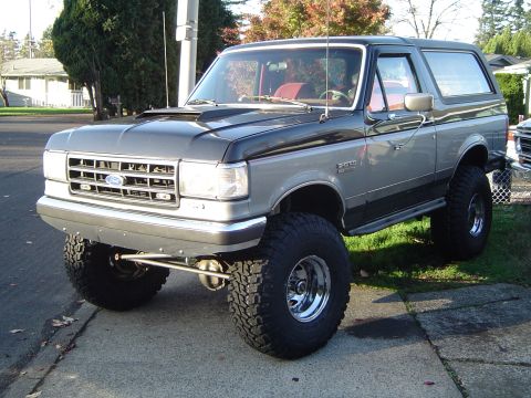

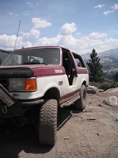
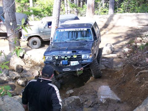
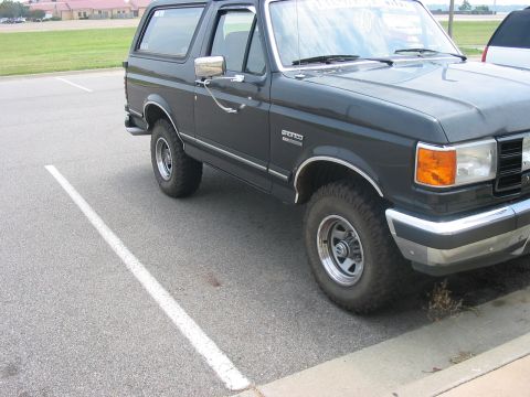

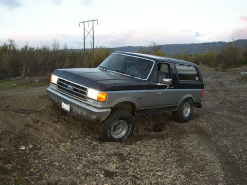
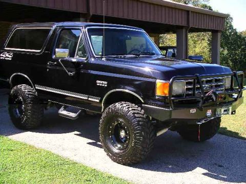

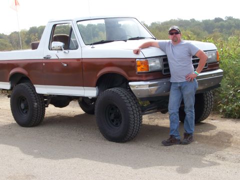
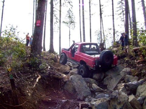
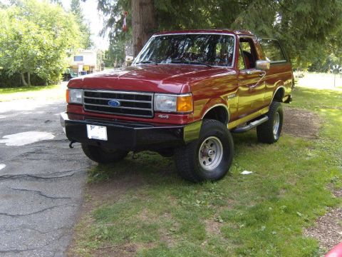
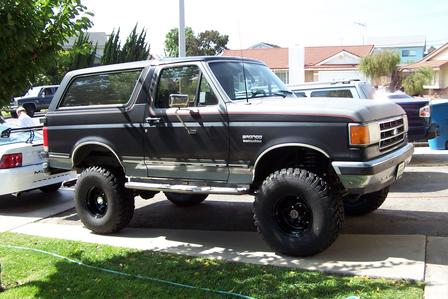



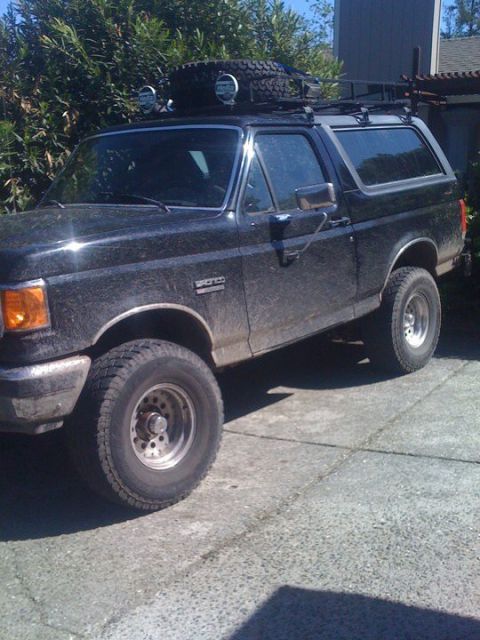
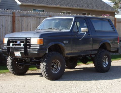
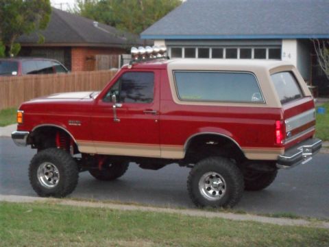
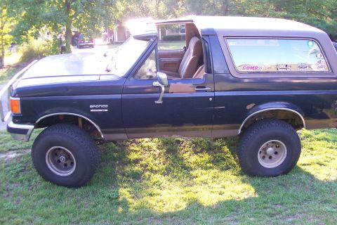
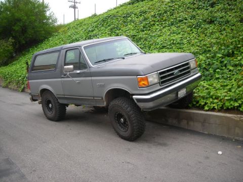
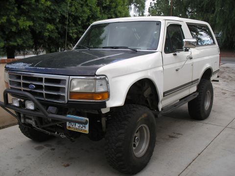
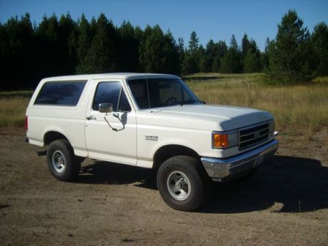
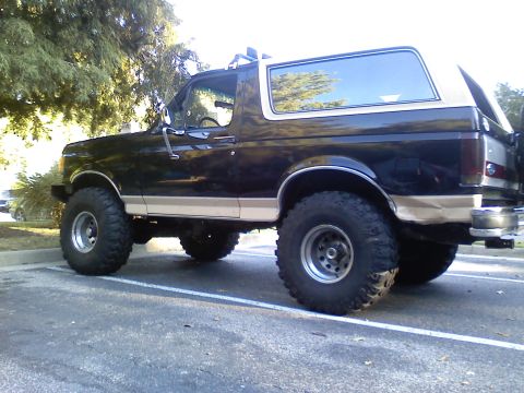
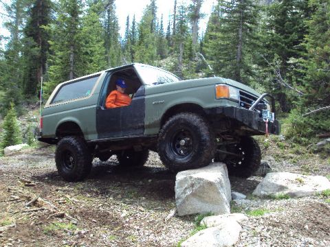

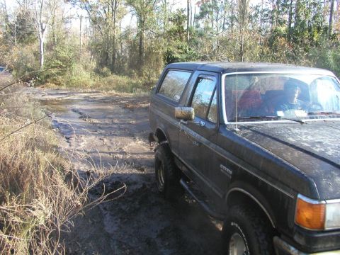
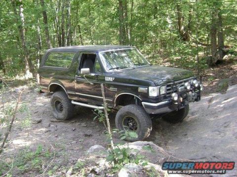

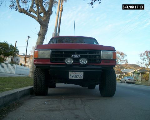

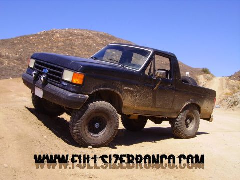
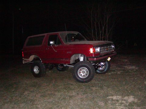
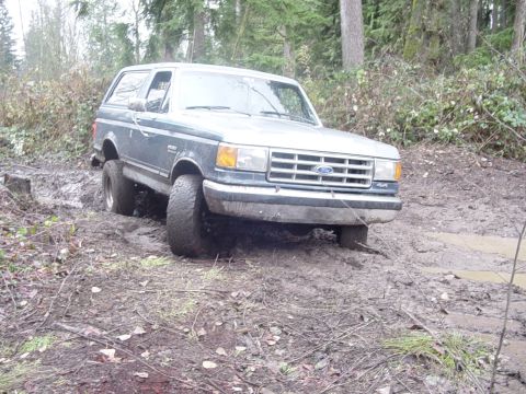
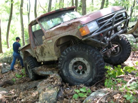

Full year-by-year change log: 1987-1991 Ford Bronco
This log tracks the running and model-year changes to the fourth-generation Ford Bronco (1987-1991), the "Bricknose" full-size wagon, at the level of body, engine, fuel system, drivetrain, axle, and brakes. It is assembled from Ford factory shop manuals, parts catalogs, and Bronco/F-series owner literature for the 1987-1991 model years, VIN and door data-plate decoding for engine, axle, and trim verification, period road tests and factory specification material, and established Bronco reference works and owner registries.
1987
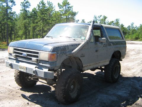
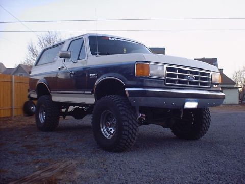
- Fourth generation introduced. The 1987 Ford Bronco opened the fourth generation on the redesigned F-series "Bricknose" body, with a flush, aerodynamic front clip and flush headlamps replacing the earlier "Bullnose" face. The Bronco kept its full-size two-door wagon form with a removable fiberglass rear hardtop over a 104.7-inch wheelbase, sharing its structure with the F-150 ahead of the B-pillar.
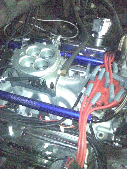
- Electronic fuel injection on the 4.9L six. The 1987 Bronco's 4.9L (300) inline-six gained electronic fuel injection, one of the year's defining mechanical changes. The 5.0L (302) V8 carried over its existing electronic (throttle-body) fuel injection from the third generation.
- 5.8L V8 stayed carbureted. The 1987 Bronco's optional 5.8L (351 Windsor) V8 remained carbureted for the model year and gained EFI for 1988.
- Standard rear-wheel anti-lock brakes. The 1987 Bronco gained standard rear-wheel anti-lock brakes (RABS), a rear-axle ABS system that reduces rear-wheel lockup under hard braking, paired with front disc and rear drum brakes.
- Axles and front suspension. The 1987 Bronco used a Dana 44 Twin-Traction Beam (TTB) independent front axle and a Ford 8.8-inch semi-floating rear axle. The rear axle was the Ford 8.8-inch this year; the previous generation had used a 9-inch rear axle. The TTB front suspension carried over from the third generation and was not new to this generation.
- Drivetrain. The 1987 Bronco offered manual and automatic transmissions and used four-wheel drive with a two-speed transfer case.
- Trims. The 1987 Bronco was offered in Custom, XLT, and Eddie Bauer trim levels, with Custom as the base trim below XLT and Eddie Bauer.
1988
- 5.8L V8 gained EFI. The 1988 Bronco's 5.8L (351 Windsor) V8 adopted multi-port electronic fuel injection, completing the fuel-injected engine lineup alongside the 4.9L six and 5.0L V8.
- Base trim renamed XL. The base trim that had been called Custom for 1987 was renamed XL for 1988, sitting below XLT and Eddie Bauer.
- Five-speed overdrive manual. Around 1988 the Mazda-built M5OD five-speed overdrive manual replaced the older four-speed manual transmission.
- Carryover otherwise. The 1988 Bronco continued the Bricknose body with the Dana 44 TTB front axle, Ford 8.8-inch semi-floating rear, front disc and rear drum brakes with standard rear-wheel ABS, four-wheel drive with a two-speed transfer case, and XL, XLT, and Eddie Bauer trims, with minor trim and equipment revisions.
1989
- Mostly carryover. The 1989 Bronco remained a Bricknose fourth-generation wagon with the fuel-injected 4.9L six, 5.0L V8, and 5.8L V8, receiving running interior and equipment updates.
- Hardware unchanged. The 1989 Bronco kept the Dana 44 TTB front axle, Ford 8.8-inch semi-floating rear, front disc and rear drum brakes with standard rear-wheel ABS, four-wheel drive with a two-speed transfer case, and XL, XLT, and Eddie Bauer trims.
1990
- E4OD four-speed automatic introduced. The 1990 Bronco gained the E4OD, a four-speed electronically controlled automatic with overdrive, which replaced the older three-speed automatic in many configurations.
- Engines unchanged. The 1990 Bronco continued with the fuel-injected 4.9L (300) inline-six, 5.0L (302) V8, and 5.8L (351 Windsor) V8.
- Hardware unchanged. The 1990 Bronco kept the Dana 44 TTB front axle, Ford 8.8-inch semi-floating rear, front disc and rear drum brakes with standard rear-wheel ABS, four-wheel drive with a two-speed transfer case, and XL, XLT, and Eddie Bauer trims.
1991
- Final Bricknose year. The 1991 model year was the last for the fourth-generation Bricknose Bronco before the 1992 fifth-generation redesign.
- Carryover powertrain. The 1991 Bronco continued with the fuel-injected 4.9L six, 5.0L V8, and 5.8L V8, with the E4OD four-speed overdrive automatic available.
- Nite appearance package. The blacked-out "Nite" appearance package was offered for 1991.
- Hardware unchanged. The 1991 Bronco kept the Dana 44 TTB front axle, Ford 8.8-inch semi-floating rear, front disc and rear drum brakes with standard rear-wheel ABS, four-wheel drive with a two-speed transfer case, and XL, XLT, and Eddie Bauer trims.