Home/
Registry/
Ford/
Bronco/
1987-1991/
“Eddie Bauer”/
Photo
supermotors.net/registry/media/1109652
1973-1974 Ford Point-Type Ignition System Circuit Diagram - Coil & Distributor

Reference · 1987-1991 BroncoAll 175 wiring diagrams





Wiring diagram of a conventional 1973-1974 point-type ignition system showing battery, coil, distributor, and spark plug with primary and secondary circuits.
Part of 1987-1991 Ford Bronco Wiring Diagrams
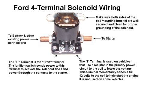
This document is a labeled schematic diagram of a typical conventional point-type ignition system circuit as used on 1973-1974 vehicles. The diagram illustrates the complete ignition circuit, distinguishing between the primary circuit (shown as a solid heavy line) and the secondary circuit (shown as a dashed line) via a legend. Components labeled in the diagram include the ignition switch (with IGNITION, START, and BATTERY terminal positions), a terminal connector, the primary resistance wire, a quick disconnect, the starter relay (marked with S and I terminals), the battery (with + and − terminals shown), the ignition coil, the distributor with cap and spark plug wires, and a spark plug. Grounds are indicated at the battery negative terminal and near the distributor. A reader can learn how the primary (low-voltage) side of a points ignition system routes power from the battery through the ignition switch, resistance wire, and relay to the coil, and how the secondary (high-voltage) side carries spark energy from the coil through the distributor cap to the spark plugs. The caption at the bottom, partially cropped, identifies it as a typical ignition system circuit used on conventional (1973-1974) point-type systems.
This document covers 1973-1974, which may differ from this 1990 Ford Bronco.
Is this accurate? Sign in to help verify it.
Frequently asked questions
- What years does this point-type ignition diagram cover?
- The caption states it is a typical ignition system circuit as used on conventional (1973-1974) point-type systems.
- How are the primary and secondary circuits shown in the diagram?
- A legend indicates the primary circuit is drawn as a solid heavy line and the secondary circuit as a dashed (dotted) line.
- What components are included in this ignition circuit?
- The diagram labels the ignition switch (with IGNITION, START, and BATTERY positions), terminal connector, primary resistance wire, quick disconnect, relay, battery, coil, distributor, and spark plug.
- Where does the primary resistance wire connect in the circuit?
- The primary resistance wire runs from the ignition switch area (after the terminal connector and quick disconnect) to the ignition coil.
- What terminals are shown on the relay?
- The relay is drawn with terminals marked 'S' and 'I'.






No comments yet.