Home/
Registry/
Mazda/
MX-3/
1992-1996/
“AKA Eunos Presso”/
Photo
supermotors.net/registry/media/921602
Engine Oil Pump Diagram - Inner/Outer Rotor, Pressure Regulator & Oil Flow
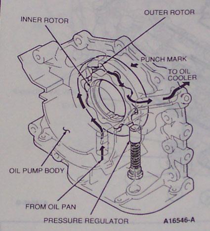
Reference · 1992-1996 MX-3All 3 exploded parts diagrams
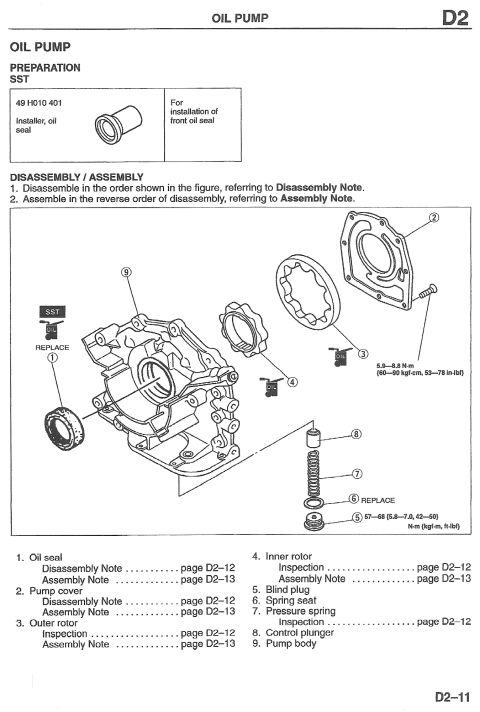
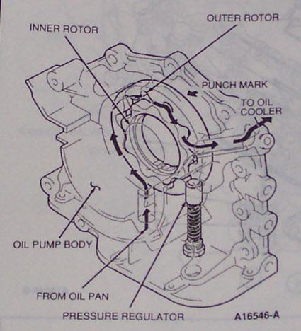
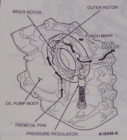
Oil pump component diagram identifying inner and outer rotors, pump body, pressure regulator and oil flow paths.
Part of 1992-1996 Mazda MX-3 Exploded Parts Diagrams
This document is a labeled line-art diagram of an engine oil pump assembly, apparently reproduced from a service manual page (figure reference A16546-A). The illustration shows the oil pump body mounted on the front of an engine block, with the pump cover removed to expose the gerotor-style pumping elements. Callouts identify the INNER ROTOR and OUTER ROTOR, a PUNCH MARK on the rotor (an orientation/assembly reference), the OIL PUMP BODY casting, and the PRESSURE REGULATOR (a spring-loaded relief valve shown exploded out of its bore). Arrows drawn through the diagram trace oil flow: oil enters FROM OIL PAN, passes through the rotor set, past the pressure regulator, and exits TO OIL COOLER. A reader can learn the internal layout of the oil pump, the direction of oil flow through the pump and regulator circuit, the location of the pressure relief/regulator valve, and that the rotors carry a punch mark that should be observed during reassembly. No torque values, part numbers (other than the figure code), clearances, or year/model applicability statements appear on this page; it is purely an identification and flow-path diagram.
Is this accurate? Sign in to help verify it.
Frequently asked questions
- What components are identified in this oil pump diagram?
- The diagram labels the inner rotor, outer rotor, punch mark, oil pump body, pressure regulator, the inlet from the oil pan, and the outlet to the oil cooler.
- Where does the oil pump draw oil from and where does it send it?
- Arrows show oil entering the pump from the oil pan and exiting to the oil cooler.
- Where is the pressure regulator located?
- The pressure regulator is shown as a spring-loaded valve installed in a bore in the oil pump body, in the oil flow path after the rotors.
- What is the punch mark shown on the rotor?
- The diagram points out a punch mark on the outer rotor area; it is called out as an identification/orientation mark, though the page gives no further instructions about it.

No comments yet.