MGB SU Carburetter Components Exploded Parts Diagram - Workshop Manual p132
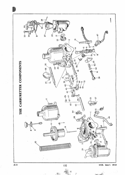
Exploded parts diagram of MGB carburetter components showing pistons, jets, floats and linkages with numbered references.
This is page 132 (section reference D.10) from the MGB workshop manual, titled 'The Carburetter Components'. The page consists entirely of a large exploded-view line drawing of the twin SU carburetter assembly and its associated hardware. Individual components are identified by numbered callouts ranging from 1 to 72 (some numbers such as 48-50 and 52 are not visible on this page), pointing to items such as the carburetter body, suction chamber (dashpot), piston, piston spring, jet assembly, float chamber, float, needle, throttle spindle, linkage levers, springs, washers, screws, bolts, and fuel pipe fittings. No text legend or parts list accompanies the numbers on this page, the key identifying each numbered part presumably appears on an adjacent page of the manual (the same album contains p131 and p134). The footer identifies the source as 'MGB. Issue 5. 69615', confirming the document is from a factory MGB workshop manual. A reader can use this page to visually identify and locate each carburetter component and understand the order of assembly/disassembly, but must cross-reference the numbered key elsewhere in the manual for part names.
Is this accurate? Sign in to help verify it.
Frequently asked questions
- What does this page of the MGB workshop manual show?
- It shows 'The Carburetter Components', a full-page exploded-view diagram of the MGB carburetter assembly with numbered callouts identifying each part.
- Does this page include a parts list or legend for the numbered components?
- No. The page contains only the exploded drawing with callout numbers (1 through 72, with some numbers absent); the key naming each part is not printed on this page.
- What manual section and page is this diagram from?
- It is page 132, section reference D.10, from the MGB workshop manual, marked 'MGB. Issue 5. 69615' in the footer.
- How many numbered components are shown in the carburetter exploded diagram?
- Callout numbers run from 1 to 72, though a few numbers (such as 48, 49, 50 and 52) do not appear on this page, so roughly 68 numbered items are visible.
Comments
More from this build
No comments yet.