Home/
Registry/
Ford/
F-150/
1987-1991/
1991 Ford F-150/
Photo
supermotors.net/registry/media/1016366
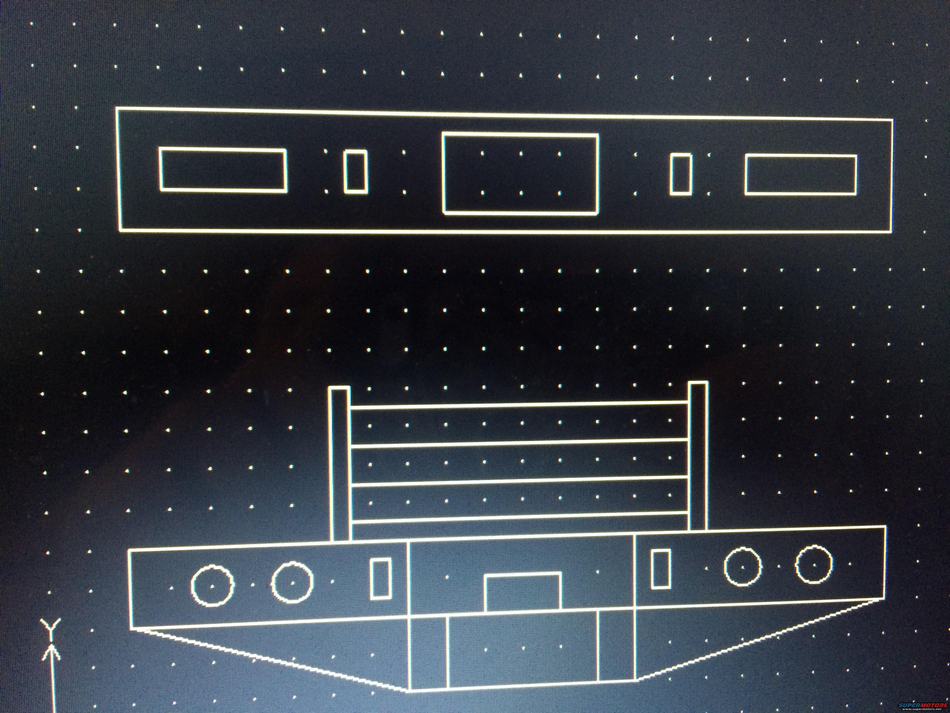
1991 Ford F-150 Custom Bumper CAD Blueprint - Wireframe Design Drawing
Reference · 1987-1991 F-150All 1 blueprints
CAD line drawing of a bumper shown in front and isometric views on a dotted grid layout.
Part of 1987-1991 Ford F-150 Blueprints
This document is a photograph of a computer monitor displaying a CAD wireframe blueprint, uploaded to the gallery of a 1991 Ford F-150. It shows two views of what appears to be a custom heavy-duty bumper or bumper/grille-guard fabrication design. The upper drawing is a flat face view of a long rectangular plate with five cutouts: two wide rectangular openings at the outer ends, two small vertical rectangular slots, and one large central rectangular opening. The lower drawing is a perspective-style rendering of the assembled piece: a wide bumper body with angled, tapered lower ends, four circular cutouts (presumably for round lights, two per side), two small rectangular slots, and a central notch, topped by a rail or push-bar structure consisting of two vertical uprights joined by three to four horizontal cross members. Aside from a 'Y' coordinate-axis marker in the lower-left of the screen, the drawing contains no text, dimensions, part numbers, torque specs, or annotations of any kind. A reader can learn the general shape, cutout layout, and configuration of the planned bumper design, but no measurements or vehicle applicability can be determined from the document itself.
Is this accurate? Sign in to help verify it.
Frequently asked questions
- What does this blueprint show?
- It shows a CAD wireframe drawing of what appears to be a custom bumper design: a flat face view of a plate with rectangular cutouts, and a perspective view of the bumper with four round cutouts, angled ends, and an upper rail/push-bar structure with vertical uprights and horizontal cross bars.
- Are there any dimensions or measurements on this drawing?
- No. The drawing contains no visible dimensions, measurements, or annotations, only the wireframe geometry and a 'Y' axis marker.
- How many light/circular cutouts are shown in the bumper design?
- Four circular cutouts are visible in the perspective view, two on the left side and two on the right side of the bumper face.
- Does the document list any part numbers or specifications?
- No part numbers, torque values, or specifications appear anywhere in the drawing; it is purely a graphical CAD sketch.

No comments yet.