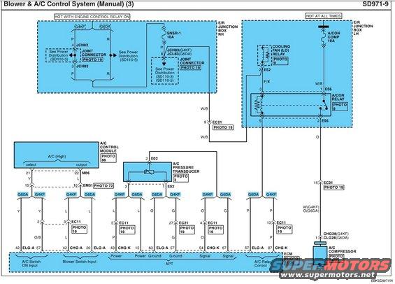
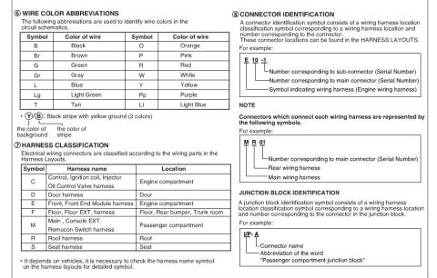
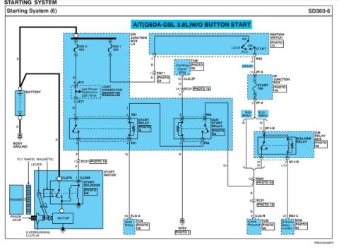
This diagram illustrates the blower and A/C control system, detailing component connections and functions.
Blower 3. NC Control System (Manual) (3) SD97I-9 How mm mmoLnsLn w MoYAYALLYMEs . La. . um-w . 1:? E . m1 1 1' "WE? L Mm . m L 1 . Imam manic)! L'LLL.ZLW 1 . Egg-111V _ W05, . . ; mu 1 1 - L " 45mm, 4 1 1 45mm, 1 . 1 wra ; own 1 Wm m mm. mm New, from 2 m L. W. m ism: Z, Viz m vlmsnuczk mm V l a 5 (c2: 5 "WTW_ :[7 r: m m sum 5w: W W. W m. W. W W m. mm W MW, V v L L L L o e o G , , mm, Z 5 s (c 27 Eon . {cu m am New Mom mm mm Imam v- u L. L. u WNW, or: L , e o u L anmcnm a LL67. 57 L2 m. m EL 43 cm L5 ML .Lc , m "20.1 comm. . H,_/ pmmm am .mw mo %/ . m2; . mm NW. .. : ownnm A Eumm Y m
Comments
More from this build
No comments yet.