Home/
Registry/
Hyundai/
Genesis Coupe/
2010-2016/
“Coupe”/
Photo
supermotors.net/registry/media/1171523
Hyundai Genesis Coupe 3.8L Starter Wiring Diagram A/T w/o Button Start SD360-6

Reference · 2010-2016 Genesis CoupeAll 79 wiring diagrams



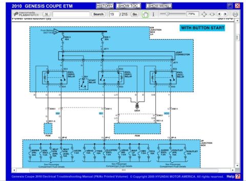
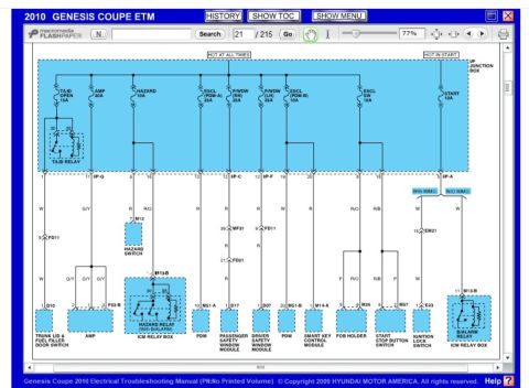
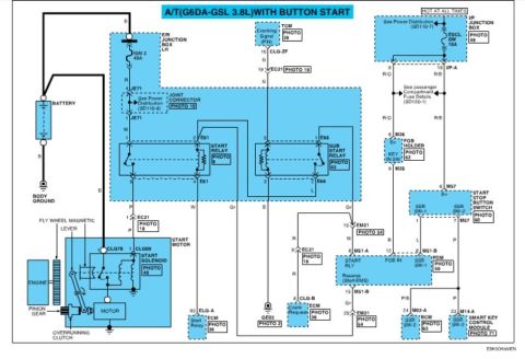
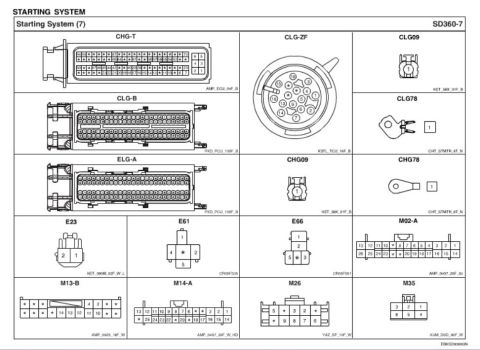








Wiring diagram of the starting system showing battery, start relays, solenoid, starter motor and ignition switch with color-coded wires.
Part of 2010-2016 Hyundai Genesis Coupe Wiring Diagrams
This is page SD360-6 from a Hyundai factory wiring diagram set, showing the Starting System (6) circuit for an A/T (automatic transmission) G6DA-GSL 3.8L vehicle WITHOUT button start (conventional key ignition). The diagram traces power from the battery through the E/R Junction Box LH (IGN 2 40A and IGN 1 30A fuses), the ignition switch (LOCK/ACC/ON/START positions), and the I/P Junction Box (START 10A fuse) to the Start Relay and Sub Start Relay, and finally to the start solenoid and starter motor. It shows the TCM providing a cranking signal (P/N), branches for vehicles with and without an immobilizer, the ICM Relay Box burglar alarm (B/Alarm) relay, ECM crank request and start relay control inputs (connectors CLG-B pin 8 and ELG-A pin 93), and BCM burglar alarm relay control (M02-C pin 22). Connector identifiers (EM11, EC21, EM21, M35, M13-B, E61, E66, JE71, CLG-ZF, CLG78, CLG09, GE03) and wire colors (B, R, P, W, G, L, Gr, L/O) are labeled throughout, along with photo references for component locations. Mechanical starter components (pinion gear, overrunning clutch, flywheel magnetic lever) are also depicted.
Is this accurate? Sign in to help verify it.
Frequently asked questions
- What fuses protect the starting circuit in this diagram?
- IGN 2 (40A) and IGN 1 (30A) in the E/R Junction Box LH, plus a START 10A fuse in the I/P Junction Box.
- Which relays are in this starting system?
- A Start Relay (connector E61, PHOTO 9), a Sub Start Relay (connector E66, PHOTO 42), and a B/Alarm Relay in the ICM Relay Box (PHOTO 48).
- What engine and transmission does this diagram apply to?
- It applies to A/T (automatic transmission) vehicles with the G6DA-GSL 3.8L engine without button start (key ignition).
- How does the ECM connect to the starting system?
- The ECM receives a Crank Request on pin 8 of connector CLG-B (via EC21 and EM21) and controls the Start Relay via pin 93 of connector ELG-A.
- What signal does the TCM provide in this circuit?
- The TCM provides a Cranking Signal (P/N) from pin 10 of connector CLG-ZF, routed through connector EC21 pin 19 with a G (green) wire.

No comments yet.