2010 Hyundai Genesis Coupe Interior Fuse Box Rear Connectors I/P-A to I/P-K
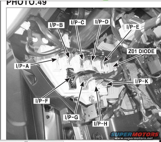
Labeled service photo identifying instrument-panel wiring harness connector locations and the Z01 diode.
This document is a labeled photograph (PHOTO.49) from a service manual showing the rear (harness) side of an interior fuse box / junction block, viewed from under the dash area of the vehicle. Arrows identify the positions of ten items: connectors I/P-A, I/P-B, I/P-C, I/P-D, I/P-E, I/P-F, I/P-G, I/P-H, and I/P-K, plus the Z01 DIODE mounted on the harness near the fuse box. The photo shows the multi-connector plugs seated into the back of the junction block, with wiring harnesses routed around it. A reader can use this photo to physically locate each I/P (instrument panel) connector on the back of the interior fuse box, for example when tracing circuits from a wiring diagram, checking connector seating, or locating the Z01 diode. No fuse amperage values, wire colors, pin numbers, or part numbers are shown—only connector position callouts. The upload is associated with a 2010 Hyundai Genesis Coupe (BK1) and appears to be part of a larger set of service manual excerpts for that vehicle.
Is this accurate? Sign in to help verify it.
Frequently asked questions
- What connectors are located on the back of the interior fuse box?
- The photo labels connectors I/P-A, I/P-B, I/P-C, I/P-D, I/P-E, I/P-F, I/P-G, I/P-H, and I/P-K on the back of the interior fuse box.
- Where is the Z01 diode located?
- The Z01 diode is shown in the wiring harness at the back of the interior fuse box, near connectors I/P-E and I/P-K.
- Does this document list fuse amperage ratings or wire colors?
- No. It is a location photo only, identifying connector positions (I/P-A through I/P-K) and the Z01 diode; no fuse ratings, wire colors, or pinouts are shown.
- Is there an I/P-I or I/P-J connector shown?
- No. The callouts skip from I/P-H to I/P-K; only connectors A through H and K are labeled in this photo.
Comments
More from this build








No comments yet.