Home/
Registry/
Hyundai/
Genesis Coupe/
2010-2016/
“Coupe”/
Photo
supermotors.net/registry/media/1172569
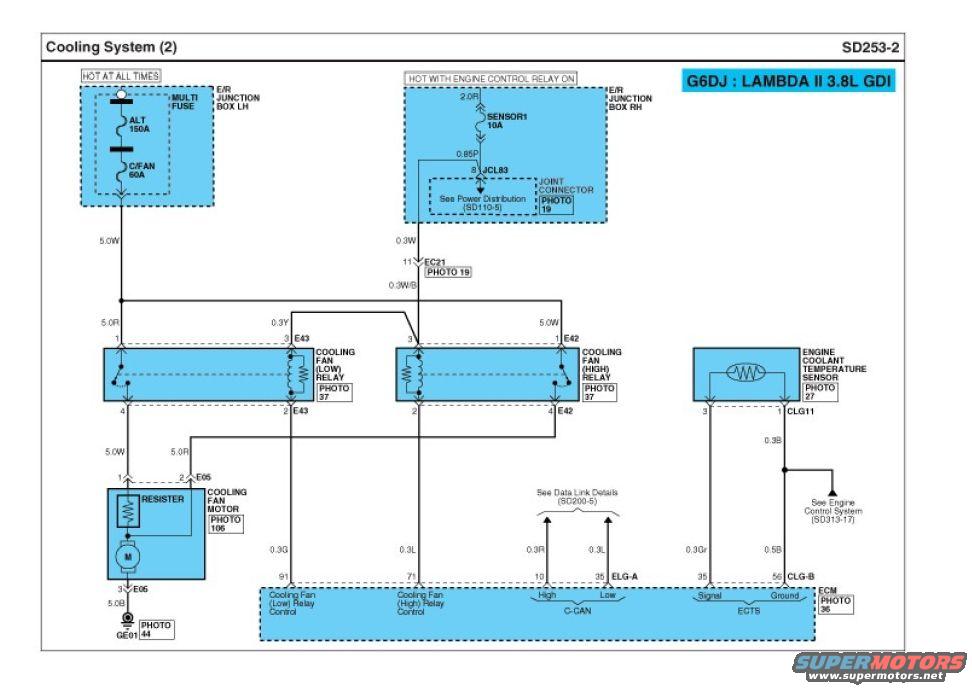
Hyundai Genesis Coupe BK2 3.8L GDI Cooling Fan Wiring Diagram SD253-2
Reference · 2010-2016 Genesis CoupeAll 79 wiring diagrams











Wiring diagram of the cooling-fan circuit (Cooling System 2) showing fan relays, fuses, resistor and coolant temperature sensor with labeled wire codes
Part of 2010-2016 Hyundai Genesis Coupe Wiring Diagrams
This is page SD253-2, "Cooling System (2)," a factory-style wiring diagram for the G6DJ Lambda II 3.8L GDI engine (Hyundai Genesis Coupe BK2 per uploader filename). It shows the engine cooling fan circuit: battery power ("HOT AT ALL TIMES") feeds through the E/R Junction Box LH multi-fuse (ALT 150A, C/FAN 60A) to the cooling fan (low) and (high) relays. Switched power ("HOT WITH ENGINE CONTROL RELAY ON") passes through the SENSOR1 10A fuse and joint connector JCL83 to energize the relay coils via connector EC21. The relays supply the cooling fan motor (connector E05), which incorporates a resistor for low-speed operation and grounds at GE01. The ECM controls both relays via pins 91 (low relay control, 0.3G wire) and 71 (high relay control, 0.3L wire), reads the engine coolant temperature sensor (connector CLG11) on ECM pins 35 (signal) and 56 (ground), and communicates on C-CAN (pins 10 high, 35 low). Wire sizes/colors (5.0W, 5.0R, 0.3Y, 0.3W/B, 0.3Gr, 0.5B, etc.), connector numbers (E05, E42, E43, EC21, CLG11), and cross-references to Power Distribution SD110-5, Data Link Details SD200-5, and Engine Control System SD313-17 are given, plus photo references for component locations.
Is this accurate? Sign in to help verify it.
Frequently asked questions
- What fuses protect the cooling fan circuit on the 3.8L GDI Genesis Coupe?
- The C/FAN 60A multi-fuse in the E/R Junction Box LH powers the fan relays, and the SENSOR1 10A fuse in the E/R Junction Box RH (hot with engine control relay on) powers the relay coils. An ALT 150A multi-fuse is also shown in the same box.
- Which ECM pins control the cooling fan relays?
- ECM pin 91 controls the cooling fan (low) relay via a 0.3G wire, and pin 71 controls the cooling fan (high) relay via a 0.3L wire.
- Where does the cooling fan motor connect and ground?
- The cooling fan motor uses connector E05: pin 1 (5.0W) from the low relay, pin 2 (5.0R) from the high relay, and pin 3 grounds via a 5.0B wire at ground point GE01.
- How is the engine coolant temperature sensor wired to the ECM?
- The ECTS (connector CLG11) sends its signal on a 0.3Gr wire to ECM pin 35 and grounds through a 0.5B wire to ECM pin 56 (CLG-B), with a 0.3B branch referenced to the Engine Control System (SD313-17).
- Which engine does this diagram apply to?
- The diagram is labeled 'G6DJ : LAMBDA II 3.8L GDI'.

No comments yet.