Hydraulic Block Pressure Measuring Method - Relief Valve Test Diagram (14.2 MPa)

hydraulicsView all 5
Service manual page illustrating the pressure measuring method with a hydraulic block, ports and an attached pressure gauge.
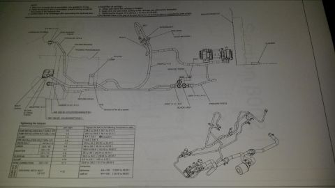
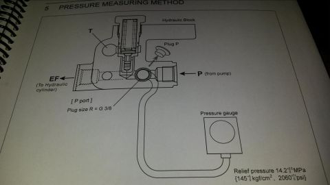
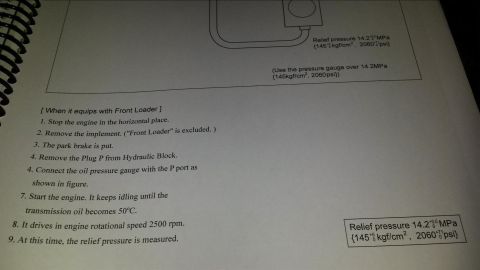
This document is a page from a spiral-bound service/reference manual, titled section "5 PRESSURE MEASURING METHOD." It shows a cutaway schematic of a hydraulic block containing a relief valve. The diagram labels the block's ports: P (pressure inlet from the pump), T (tank/return passage), and EF (outlet to the hydraulic cylinder). It identifies "Plug P," which is removed from the P port to connect a test pressure gauge; the plug thread size is given as R = G 3/8. A hose from the P port runs to an external pressure gauge, illustrating the gauge hookup for measuring system pressure. The key specification stated is the relief pressure: 14.2 +0.5/0 MPa, equivalent to 145 +5/0 kgf/cm² or 2060 +71/0 psi. A technician can use this page to learn where to tap into the hydraulic circuit for pressure testing, what fitting size is required for the gauge adapter, and what relief-valve pressure reading indicates a properly functioning system. The page appears to be one of a two-page set ("Pressure measuring 1 of 2") and complements a hydraulic layout diagram from the same album.
Is this accurate? Sign in to help verify it.
Frequently asked questions
- What is the specified relief pressure in this diagram?
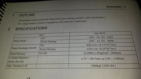
- Relief pressure is 14.2 +0.5/0 MPa, equal to 145 +5/0 kgf/cm² or 2060 +71/0 psi.
- Where do you connect the pressure gauge to measure hydraulic pressure?
- Remove Plug P from the P port on the hydraulic block and connect the pressure gauge hose there.
- What thread size is the P port plug?
- The plug size is R = G 3/8.
- What do the port labels on the hydraulic block mean?
- P is the inlet from the pump, EF is the outlet to the hydraulic cylinder, and T is the tank/return passage shown in the block.






No comments yet.