Driveline Angle Set Up Diagram - Driveshaft & U-Joint Angle Schematic
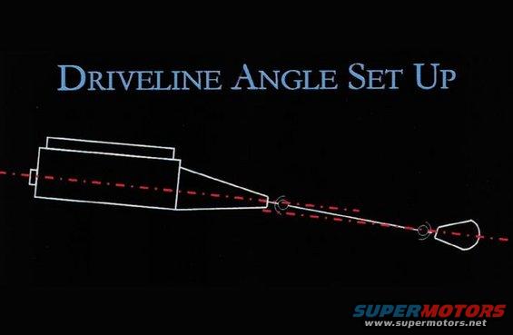
Simple schematic titled Driveline Angle Set Up illustrating the working angle line through the transmission, driveshaft and pinion.
This document is a simple black-background schematic titled "Driveline Angle Set Up." It contains no tables, part numbers, or numeric specifications, only an illustrative side-view line drawing. The drawing depicts a powertrain in profile: an engine and transmission assembly on the left tapering to a tailshaft output, a driveshaft connecting through two U-joints (drawn as small circles), and a rear axle pinion/differential housing on the right. Two red dash-dot reference lines are overlaid: one representing the engine/transmission crankshaft centerline and another representing the driveshaft/pinion axis. The intersection of these lines at the U-joint locations illustrates the working angles that must be considered when setting up a driveline. A reader can learn conceptually how driveline angles are visualized, that the transmission output centerline and the driveshaft/pinion centerline form angles at the front and rear U-joints, but the diagram provides no specific target angle values, measurement procedures, or tolerances. It appears to be a generic instructional graphic (likely from a magazine or tech article) rather than a vehicle-specific factory document, so it does not state applicability to any particular year, make, or model, and nothing in it contradicts its use as a reference for the uploader's 2001 Ford Ranger.
Is this accurate? Sign in to help verify it.
Frequently asked questions
- What does this driveline angle set up diagram show?
- It shows a side-view schematic of an engine/transmission, driveshaft, and rear pinion with red dash-dot centerlines through the transmission output axis and the driveshaft/pinion axis, illustrating the angles formed at the U-joints.
- Does the diagram give specific driveline angle values or tolerances?
- No. The diagram contains no numeric angle values, measurements, or tolerances, it is purely an illustrative concept drawing.
- Where are the U-joints represented in the diagram?
- They are drawn as small circles at each end of the driveshaft, one at the transmission tailshaft and one at the rear differential pinion, where the two red centerlines intersect.
- Is this diagram specific to a particular vehicle?
- No. The document names no year, make, model, or part numbers; it is a generic driveline angle illustration.
Comments
More from this build



No comments yet.