Home/
Registry/
Ford/
Bronco/
1978-1979/
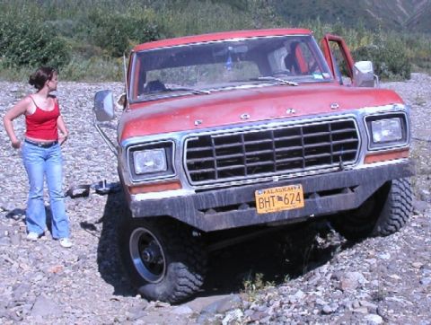
“Left for Dead”/
Photo
supermotors.net/registry/media/1097623
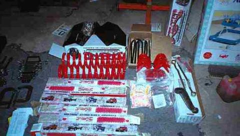
Specialty Top Co. installation instructions for Bronco 1978-1979…

Installation instructions document for a Bronco convertible top from Specialty Top Co.
TOP IN ST ALLATiON INSTRUCTIONS CO k. BRONCO 1 978-1 979 ' T7 . Thank PART #332-01 0 3? you for purchasing Specialtys Co for nvertlble Top for your Bronco. It h , vidfzt anti;;?fg;::r-Flal::fetre:d and follow, precisely, all lnstallatlonawmgtfsrsggg 5' enms - eo osoma res lt' ' occupants in a potentially hazardous situatiorr. u m a poor fitting top and could place a 3 TOOLS REQUIRED: Butt both pieces of tailgate aluminum (items 4 8.5) together on top edge of tailgate. Center from left to right and 1/2 3/8 WRENCH 7/16" WRENCH from the rear of the bed ' .. . y aluminum to the rear edge 0! 8 PRILL BIT 13% gngSBiQREWDRIVER tailgate aluminum. Making sure that tailgate aluminum is 3)? DRILL BIT ECTRIC DRILL parallel With tailgate, mark and drill 1/8 holes using tailgate 1/2 DRILL BIT EL C aluminum as a template. Secure to tailgate with #10 x 1/2" 8' TAPE MEASURE RUBBING AL OHOL sheet metal screWS (Item 2). See gure 1. Step 2. Bow Mount. Measure 27 from tail ate inset and INSTALLAT'ON TIPS place rear of bow mount (Item 6) at this pogit. mm the bow . . mount ush with inside edge of body, mark and drill two Before you begin installing this top, here are a few tips 10 5/32" holes. Only one front hole and one rear hole need to make installation easrer. be drilled. Secure to top of body with #14 x 1/2" sheet metal ' screws (Item 7). Repeat for the other side. See gure 1. This top should be installed where the temperature is above 72 degrees Fahrenheit. Below this temperature, the top may contract making it difcult to install. It is normal for a top to contract and wrinkle when stored in the shipping carton. The top will relax and wrinkles will disappear within a few days of installation as fabric adjusts to shape of mounting hardware. INSTALLATION PROCEDURES: On page 3 of this instruction manual there is an assembly drawing. Please refer to it for identication of parts and assembly assistance. Also refer to page 4 to assure that all parts are included in your kit. Step 1. Body Aluminum. Locate rear body aluminum (Item 1) just outside slight drop in body edge and 2 1/ to the rear of notch in body. Using body aluminum as a template, mark and drill 1/8 holes. Secure to body with #10 x 1/2 sheet metal screws (Item 2). Butt front body aluminum (Item 3) up to rear body aluminum. Mark and drill 1/ " holes using front body aluminum as a template. Secure to body with #10 x 1/2 sheet metal screws {Item 2). See gures 1 and 2. n .nnnn
Is this accurate? Sign in to help verify it.
Comments
More from this build


No comments yet.