Ford Autolite 2100 Carburetor Exploded Parts Diagram - 1967-68 Cougar

Reference · 1967-1970 CougarAll 3 exploded parts diagrams
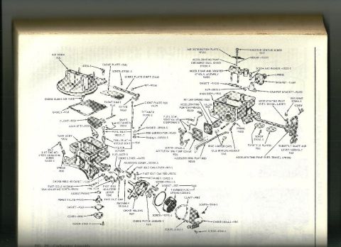

Exploded parts diagram of a carburetor detailing the choke plate, float, main body, throttle plates and accelerating pump components.
Part of 1967-1970 Mercury Cougar Exploded Parts Diagrams
This is a scanned page from a factory-style service manual showing 'FIG. 20: Carburetor Assembly,' an exploded parts diagram of a Ford/Autolite two-venturi (2100-type) carburetor. The uploader filed it in a 1967 Mercury Cougar gallery under the filename '2100carb 1968.jpg.' The diagram breaks the carburetor into its individual components with Ford basic part numbers and hardware part numbers for each callout. Major assemblies identified include the air horn (9524), choke plate and shaft (9545/9546), float and float shaft (9550/9563), main jets (9533), main body (9512), power valve (9A565), fuel inlet needle and seat (9564), thermostatic spring housing, choke housing (9849), choke piston assembly (9800), accelerating pump diaphragm (9B559), pump rod (9B524), nozzle bar and booster venturi assembly (9A523), dashpot and bracket (9B549/9B550), idle mixture needles (9541) with idle limiter caps, throttle plates (9585), and the throttle shaft and lever assembly (9581). Numerous fasteners are called out by standard hardware numbers (e.g., screws 378360-S, 31061-S, 43248-S; retainer 351825-S; nut 33923-S). A reader can use this figure to identify part names, part numbers, and the assembly order/orientation of every component when disassembling, rebuilding, or ordering parts for this carburetor.
Is this accurate? Sign in to help verify it.
Frequently asked questions
- What is the Ford part number for the main body of the 2100 carburetor?
- The main body is identified as part number 9512 in the exploded diagram.
- What part numbers are shown for the throttle plates and throttle shaft?
- The throttle plates are 9585 and the throttle shaft and lever assembly is 9581.
- What accelerating pump components are identified in the diagram?
- The diagram shows the accelerating pump diaphragm (9B559), pump cover (9528), pump rod (9B524), return spring (9636), discharge ball check (371330-S), weight (9B511), over-travel lever, and over-travel spring.
- What part number is the power valve on this carburetor?
- The power valve is shown as part number 9A565.
- What choke-related parts are listed in the exploded view?
- Choke plate (9545), choke plate shaft (9546), choke plate rod (9A399), choke lever (9A753), choke clean air tube, choke housing (9849), choke housing gasket (9583), choke piston assembly (9800), choke shield (9861), thermostatic spring housing, fast idle cam, fast idle cam lever (9F527), fast idle cam rod (9D530), and fast idle adjusting lever (9536).
No comments yet.