Power Brake Booster Push Rod Adjustment - Bendix & Midland-Ross Gauge Specs

Reference · 1967-1970 CougarAll 6 service procedures
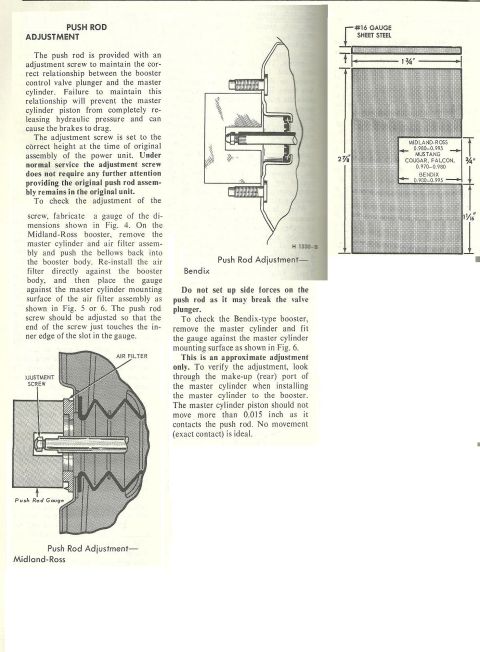
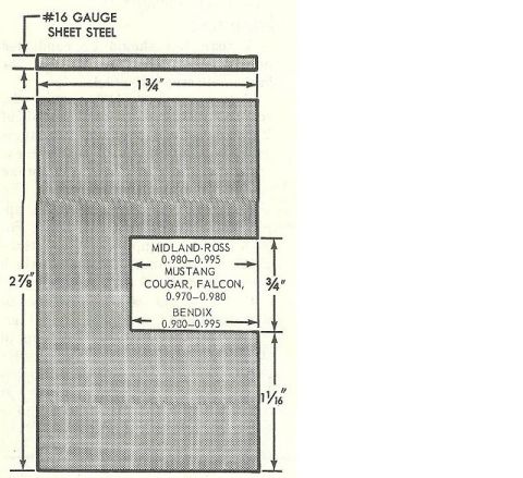
Service procedure for adjusting the brake booster push rod, with Midland-Ross and Bendix figures and a fabricated gauge drawing.
Part of 1967-1970 Mercury Cougar Service Procedures
This service procedure page describes how to check and adjust the push rod on a power brake booster (both Midland-Ross and Bendix types). The push rod's adjustment screw maintains the correct relationship between the booster control valve plunger and the master cylinder; if incorrect, the master cylinder piston cannot fully release hydraulic pressure and the brakes can drag. The screw is factory-set and normally needs no attention unless the original push rod assembly is replaced. To check adjustment, the reader fabricates a gauge from #16 gauge sheet steel per the dimensioned drawing (1-3/4" wide, 2-7/8" tall, with a 3/4" slot and gauge depths of 0.980-0.995 for Midland-Ross, 0.970-0.980 for Mustang/Cougar/Falcon, and 0.980-0.995 for Bendix). For the Midland-Ross booster, the master cylinder and air filter are removed, the bellows pushed back, the air filter reinstalled against the booster body, and the gauge placed against the master cylinder mounting surface; the screw is set so its end just touches the inner edge of the gauge slot. For the Bendix booster, the gauge is fitted directly against the master cylinder mounting surface. The article warns against side forces on the push rod and notes final verification: the master cylinder piston should move no more than 0.015 inch (ideally zero) when the master cylinder is installed.
Is this accurate? Sign in to help verify it.
Frequently asked questions
- Why does the brake booster push rod need to be adjusted correctly?
- The adjustment screw maintains the correct relationship between the booster control valve plunger and the master cylinder. If this relationship is wrong, the master cylinder piston cannot completely release hydraulic pressure and the brakes can drag.
- What are the gauge dimensions for checking push rod adjustment?
- The gauge is made from #16 gauge sheet steel, 1-3/4" wide by 2-7/8" tall, with a 3/4" slot section and a 1-1/16" lower section. Slot depths are 0.980-0.995 for Midland-Ross, 0.970-0.980 for Mustang, Cougar and Falcon, and 0.980-0.995 for Bendix.
- How do I check push rod adjustment on a Midland-Ross booster?
- Remove the master cylinder and air filter assembly, push the bellows back into the booster body, reinstall the air filter directly against the booster body, then place the gauge against the master cylinder mounting surface of the air filter assembly. Adjust the push rod screw so its end just touches the inner edge of the slot in the gauge.
- How is the push rod adjustment verified after using the gauge?
- The gauge gives an approximate adjustment only. Look through the make-up (rear) port of the master cylinder when installing it to the booster; the master cylinder piston should not move more than 0.015 inch as it contacts the push rod. No movement (exact contact) is ideal.
- What caution applies when adjusting the push rod?
- Do not set up side forces on the push rod, as it may break the valve plunger.
No comments yet.