12V/Ground Triggered Tach Adapter Wiring Diagram - Relay + TIP31C/TIP120

Wiring diagram of a relay-based tach circuit with a 1k resistor, TIP31c/TIP120 transistor and a connection legend.
This document is a screenshot of a forum post (#35, dated April 6, 2011) from the MR2OC (Toyota MR2 Owners Club) community by member 'scarecrowX' (joined March 2, 2004; 4,905 posts). It presents a wiring diagram for a DIY 12V/ground-triggered tachometer adapter built from a standard automotive relay coil and a transistor (either a TIP31C or TIP120 in a TO-220 package, with pins labeled 1-Base, 2-Collector, 3-Emitter). The circuit shows 12V feeding the relay's pin 86 and, through a 1k resistor, the transistor's base circuit; the ECU tachometer output drives pin 30, ground goes to pin 87, and the tach signal is taken from pin 85. A note advises that the relay's contact should be removed to prevent clicking. The connection legend reads: 85 - Tach, 86 - 12v, 87 - Ground, 30 - ECU tachometer output. A reader learns how to adapt an ECU tach output signal to drive a tachometer using inexpensive relay and transistor components, including which relay terminals to use and which transistor pinout applies.
Is this accurate? Sign in to help verify it.
Frequently asked questions
- Which transistors can be used for this tach adapter circuit?
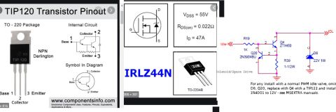
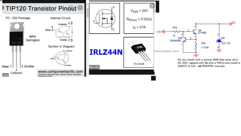
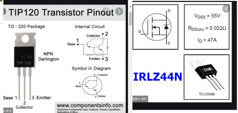
- The diagram states either a TIP31c or TIP120 in a TO-220 package can be used, with pin 1 = Base, pin 2 = Collector, pin 3 = Emitter.
- What are the relay pin connections for the tach adapter?
- Per the connection legend: pin 85 goes to the Tach, pin 86 to 12v, pin 87 to Ground, and pin 30 to the ECU tachometer output.
- What resistor value is used in the circuit?
- A 1k resistor is shown in line with the 12V supply feeding the transistor circuit.
- Why should the relay contact be removed?
- The diagram notes 'Contact should be removed to prevent clicking' — only the relay coil is used as the tach pickup element.
- Where did this diagram come from?
- It is post #35 dated Apr 6, 2011 by member scarecrowX on the MR2OC (Toyota MR2 Owners Club) forum.
Comments
More from this build

No comments yet.