MegaSquirt IRLZ44 FET Idle Valve & Solenoid Spare Drive Schematic - PWM Boost
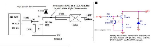
Electronic schematic of an IRLZ44 FET driver circuit for an idle/solenoid valve with resistors, diodes and transistors.
This document contains two electronic schematics related to MegaSquirt engine management installations, apparently comparing idle valve / solenoid drive circuit options. The left schematic shows an IRLZ44 MOSFET driver circuit: the MegaSquirt PCB (labeled 'MS PCB x4 V2.2 JS2 V3') drives the FET gate through a 100R resistor, with a 10K pull-down resistor from gate to ground. The FET drain switches the low side of a valve (solenoid) that is fed +12V ignition power through a fuse, with an IN4002 flyback diode from the drain back to the +12V ignition feed. A callout notes that on a V3.0 PCB you can use SPR1, which is pin 3 of the 37-pin DB connector. The right schematic shows an alternate 'Solenoid/Spare Drive' circuit using a 2N3904BU transistor (Q20) driving a ZTX450 transistor (Q4) via a 1K resistor (R19), with R39 (1-1/2W) and a 22V 1W zener diode (D8) on the IDL output line. A note states that for installs with a normal PWM idle valve, D8 and Q20 should be omitted, Q4 replaced with a TIP122, and a 1N4001 installed to 12V, referencing the MSEXTRA manuals.
Is this accurate? Sign in to help verify it.
Frequently asked questions
- How is the IRLZ44 FET wired to the MegaSquirt PCB?
- The MS PCB (x4 V2.2, JS2 V3) output connects through a 100R resistor to the FET gate, with a 10K resistor from the gate to ground. The source goes to 0V ground and the drain switches the valve, which is fed +12V ignition through a fuse.
- What flyback diode is used on the IRLZ44 valve driver circuit?
- An IN4002 diode is connected between the FET drain and the +12V ignition feed.
- Which pin can be used on a MegaSquirt V3.0 PCB for this circuit?
- The note says you can use SPR1 on a V3.0 PCB, which is pin 3 of the 37-pin DB connector.
- What changes are needed for a normal PWM idle valve on the spare drive circuit?
- The note says to omit D8 and Q20, replace Q4 with a TIP122, and install a 1N4001 to 12V — see the MSEXTRA manuals.
- What components make up the Solenoid/Spare Drive circuit?
- R19 (1K) feeds Q4 (ZTX450), driven by Q20 (2N3904BU), with R39 (1-1/2W) to ground and D8, a 22V 1W zener, from the IDL output line to ground.
Comments
More from this build





No comments yet.